前面的 硬件装置 电机 买了两种,都是320kV的,一个是小云台电机,一个是来自咸鱼的5008植保电机[卖家说单机拉力三公斤hhh实测相电阻0.15电流恐怖]。
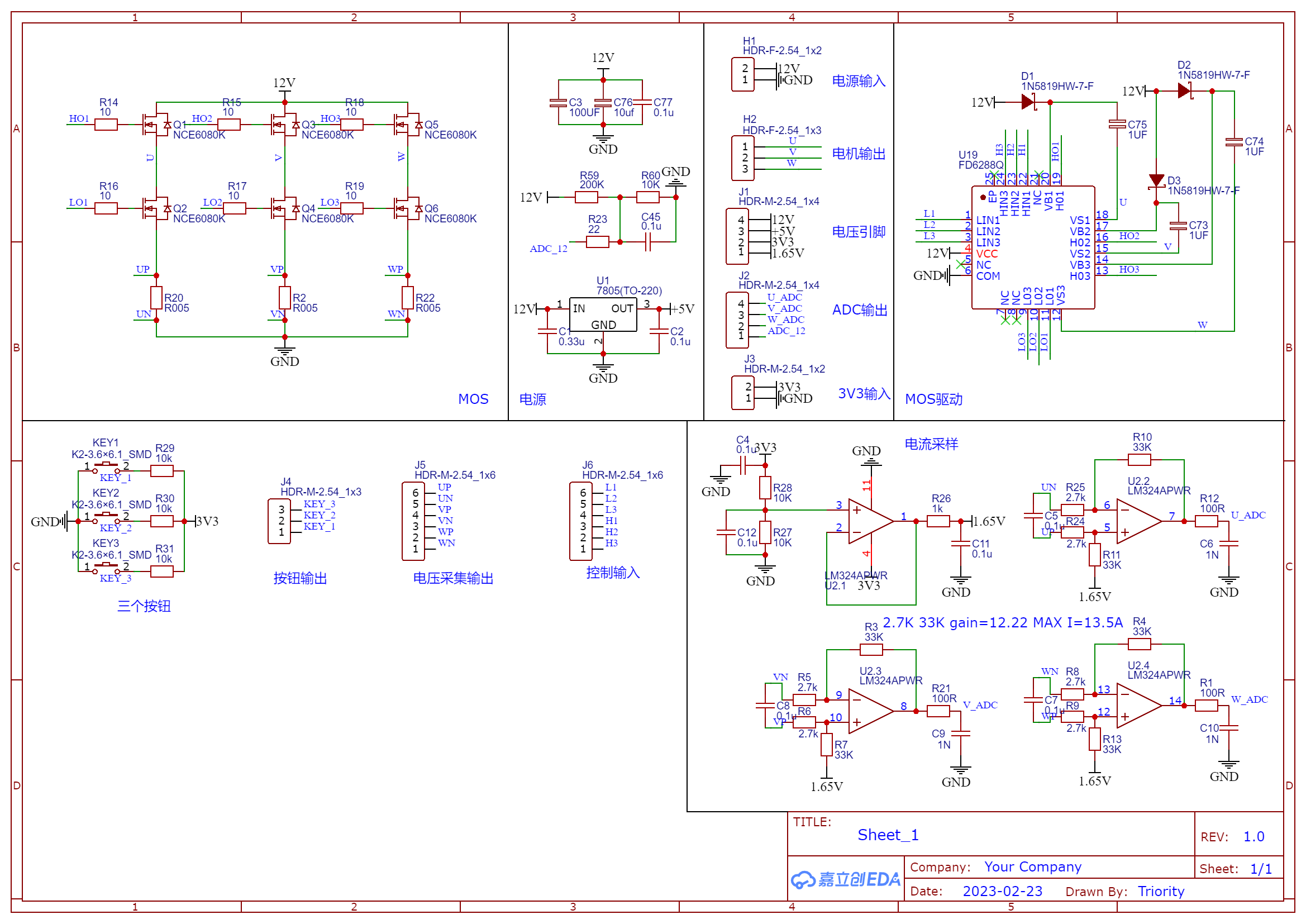
驱动 最开始自己模仿这个 画了一个驱动板simplefoc mini模块省点事。
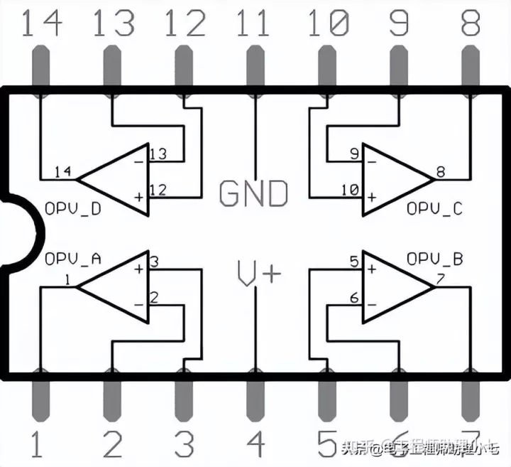
电流采样放大LM324 既然驱动板不能用hhh先用插件元件试试其他部分能不能行得通。买了几个LM324插件,尝试放大采样电阻的电压。采样电阻为R005,如果走3A电流就是0.015V
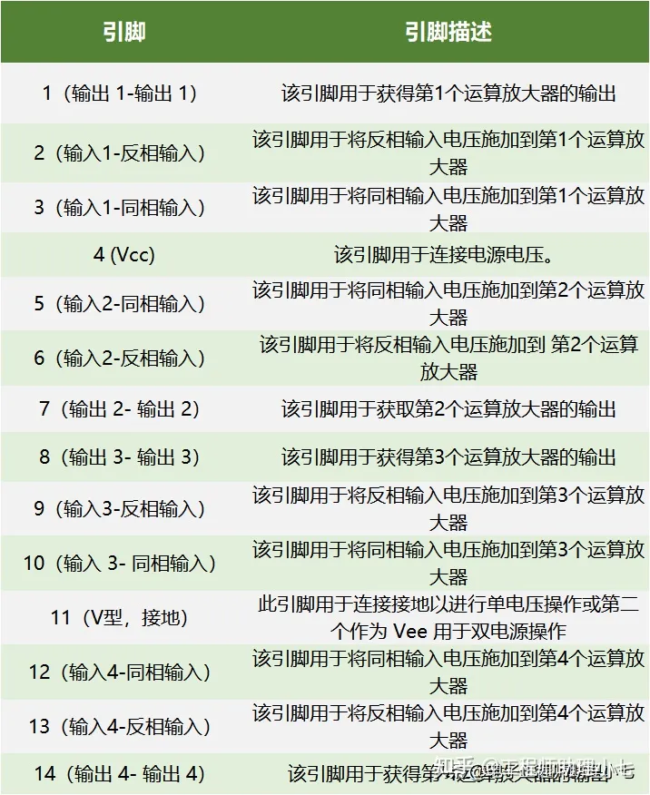
LM324 引脚图
功能图
最开始以为失败了,后来发现是我示波器用了高阻探头……换低阻之后就搞定了。
simplefoc控制 程序流程结构 include 配置电机控制器参数 首先定义电机控制器控制和使能引脚
1
2
// BLDCDriver3PWM( pin_pwmA, pin_pwmB, pin_pwmC, enable (optional)) BLDCDriver3PWM driver = BLDCDriver3PWM(11, 10, 9, 8);
然后在setup()函数中定义频率电压等
1
2
3
4
5
6
// pwm频率[Hz] driver.pwm_frequency = 20000; // 电源电压[V] driver.voltage_power_supply = 12; // 电机最大电压 driver.voltage_limit = 12;
最后在setup()函数中将电机控制器初始化
配置位置传感器 SimpleFOC支持三种常用传感器,以及自定义传感器:
编码器:光学、电容、磁性编码器(ABI)
磁性传感器:SPI、I2C、模拟或 PWM
霍尔传感器:3x霍尔探空仪、磁性传感器(UVW 接口)
这是官网提供的磁编码器(英文是Magnetic sensors)例程
基于14位SPI的磁传感器的初始化示例,例如AS5047u。
1
2
3
4
5
6
7
8
#include <SimpleFOC.h> // MagneticSensorSPI(int cs, float bit_resolution, int angle_register) MagneticSensorSPI sensor = MagneticSensorSPI(10, 14, 0x3FFF); void setup(){ // initialize magnetic sensor hardware sensor.init(); } void loop() {}
对于我使用的as5600磁编码器,将传感器定义改成这样写即可
1 MagneticSensorI2C sensor = MagneticSensorI2C(AS5600_I2C);
记得然后在setup()函数中初始化传感器
配置电流传感器 目前我在用的驱动板没有电流检测功能,也就是说这部分可以不写,但是未来驱动那个5008肯定要有的,使用也写一下
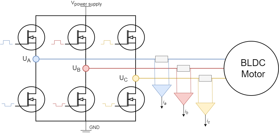
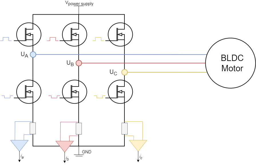
电流检测有两种,一种是In-line current sensing一种是Low-side current sensing,两者区别主要在于采集电阻的位置:
In-line current sensing
Low-side current sensing
前者简单易用,无论PWM占空比的状态如何,在这些分流电阻器上测量的电流都是电机相电流。缺点就是硬件上,这种电流检测架构需要高精度双向放大器。
而后者是最常见的电流检测技术。它不需要特殊的电流检测放大器。这种方法的主要缺点是,由于只有当相应的低侧MOSFET导通时,通过分流电阻的电流才是相电流,因此只能在这些时刻测量它。PWM频率通常为20至50 kHz,这意味着低侧MOSFET每秒打开和关闭20,000至50,000次,因此PWM设置和ADC采集之间的同步非常重要。
对于我倾向于使用第二种方案。这种方案需要注意的事情就是,首先PWM频率越高,ADC读取电流值的时间就越短,但是更高的PWM频率将产生更平滑的操作。经验法则是保持在20kHz左右。 driver.pwm_frequency = 20000;;其次,由于ADC转换必须与所有相位上产生的PWM同步,因此为所有相位生成的所有PWM必须对齐,建议确保为驱动器选择的PWM引脚都属于同一定时器
下面开始配置电流采集对象
1
2
3
4
// shunt_resistor 电流采集电阻值 // gain 放大增益 // phA/phB/phC LowsideCurrentSense current_sense = LowsideCurrentSense(0.01, 1000, A0, A1, A2);
由于电流检测要求在所有低侧MOSFET导通时(当所有相位均接地时)精确触发ADC采集,因此要在setup()将电流采集与电机配置连接,并初始化。
1
2
current_sense.linkDriver(&driver); current_sense.init();
配置电机 1 2 3 4 5 // BLDCMotor(int pp, (optional R, KV)) // - pp - 极对数 // - R - 相电阻 - 可选项 // - KV - KV值[rpm/V] - 可选项 BLDCMotor motor = BLDCMotor(7);
经验法则:KV建议将输入值设置比实际值高50-70%,或者通过实验确定的值。根据电机机械结构,适当的值将在电机额定值的100%-200%之间。
然后连接驱动器和位置或电流传感器(如果有)
1 2 3 motor.linkSensor(&sensor); motor.linkDriver(&driver); motor.linkCurrentSense(¤t_sense);
配置PWM调制类型 BLDC 电机实现了四种类型的磁场定向控制调制类型:
正弦PWM和空间矢量换向模式将产生正弦电流和平稳运行,FOC转矩控制需要正弦电流,因此必须使用这两种之一。
块换向的执行速度更快,更适合更高的速度,因此建议使用带霍尔传感器的梯形120换向。
1 2 3 4 5 6 // 选择FOC控制模式 // FOCModulationType::SinePWM; (默认) // FOCModulationType::SpaceVectorPWM; // FOCModulationType::Trapezoid_120; // FOCModulationType::Trapezoid_150; motor.foc_modulation = FOCModulationType::SpaceVectorPWM;
配置传感器和电机对准参数:电机和传感器对准的电压设置 1 motor.voltage_sensor_align = 3; // 默认为3V
配置位置传感器偏移:指定传感器绝对零点 1 motor.sensor_offset = 0; // 默认 0 rad
配置转矩控制方式 Arduino SimpleFOC库中实现了 3 种不同的转矩控制模式:
电压模式
直流电流
FOC电流1 2 3 4 // TorqueControlType::voltage(默认) // TorqueControlType::dc_current // TorqueControlType::foc_current motor.torque_controller = TorqueControlType::foc_current;
配置运动控制参数 Arduino SimpleFOC库中实现了 3 种不同的闭环控制策略:
扭矩控制
速度控制
位置/角度运动控制
此外,SimpleFOC库还实现了两种开环控制策略:
此参数没有默认值,必须在实时执行开始之前设置。
1 2 3 4 5 6 // MotionControlType::torque - 扭矩控制 // MotionControlType::velocity - 速度控制 // MotionControlType::angle - 位置/角度运动控制 // MotionControlType::velocity_openloop - 速度开环控制 // MotionControlType::angle_openloop - 位置开环控制 motor.controller = MotionControlType::angle;
配置完成 通过运行功能终止配置,该函数使用配置的值准备所有硬件和软件电机组件
配置预设参数跳过位置校准 如果使用的是绝对传感器,例如磁传感器或霍尔传感器,就可以提供传感器偏移和传感器方向以避免对齐过程:
1 2 3 // motor.initFOC(zero_electric_offset(rad), sensor_direction(CW/CCW)); // 这里给出的参数就是我在as5600编码器下使用的 motor.initFOC(3.2, Direction::CCW);
可以通过运行示例来查找这些值。find_sensor_offset_and_direction.ino
跳过电流校准 但要确保所有增益都设置良好,并且所有ADC引脚都与驱动器/电机相位对应。
1 current_sense.skip_align = true; // 默认false
实时运动控制 控制方法 Arduino SimpleFOC库的实时运动控制通过两个功能实现:
motor.loopFOC() - 低水平扭矩控制
motor.move(float target) - 高级运动控制
功能行为直接取决于使用的扭矩控制模式。如果使用电压模式,它从传感器获取电流电机角度,将其转换为电角度并变换q轴loopFOC()Uq电压命令设置电机到适当的相电压motor.voltage_qua,ub和uc。而如果将其用于FOC电流模式的直流,则读取电流传感器并运行闭环电流控制。
此功能在电压模式和电流控制模式下的执行时间都至关重要。因此,尽可能快地执行函数非常重要。
如果电机在开环中运行,此功能将不起作用
最后,一旦我们有办法设置扭矩命令(当前我q或电压uq) 到 电机 使用 FOC 算法,我们可以进行运动控制。
该方法执行算法的运动控制循环。如果由变量控制。它执行纯扭矩环路、速度环路或角度环路。
1 2 3 4 5 // 执行由电机配置的运动控制循环的函数 // 此函数不需要在每次循环执行时运行 - 取决于用途 // target:扭矩、角度或速度,或取决于电机控制器 // 如果没有配置,电机将会使用他可变的电机目标设置 motor.move(target);
它接收一个参数,该参数是当前用户定义的目标值:
如果用户运行速度闭环或速度开环,函数将解释为目标速度
如果用户运行角度闭环或角度开环,会将参数解释为目标角度
如果用户运行扭矩闭环,函数会将参数解释为目标电压或当前Iq(如果提供相位电阻)。运动控制缩减采样 对于许多运动控制应用,为每个运动控制回路运行多个转矩控制回路是有意义的。这会对平滑度产生很大影响,并可以提供更好的高速性能。1 2 // 缩减采样值 motor.motion_downsample = 5; // 次数 (默认 0 - ~)
下采样的不同值可能需要对运动参数进行一些调整
用户交互
监控功能 电机命令
位置闭环控制 原理 运行后电机就会锁定在0度位置,可以使用串口T命令设置目标角度。
1 2 3 4 5 6 7 8 9 10 11 12 13 14 15 16 17 18 19 20 21 22 23 24 25 26 27 28 29 30 31 32 33 34 35 36 37 38 39 40 41 42 43 44 45 46 47 48 49 50 51 52 53 54 55 56 57 58 59 60 61 62 63 64 65 66 67 68 69 70 71 72 73 74 75 76 77 78 79 80 #include <SimpleFOC.h> // 定义位置传感器:编码器AS5600 MagneticSensorI2C sensor = MagneticSensorI2C(AS5600_I2C); // 定义无刷电机控制器:极对数和控制引脚 BLDCMotor motor = BLDCMotor(7); BLDCDriver3PWM driver = BLDCDriver3PWM(11, 10, 9, 8); // 设置目标角度 float target_angle = 0; // 串口目标角度控制命令 Commander command = Commander(Serial); void doTarget(char* cmd) { command.scalar(&target_angle, cmd); } void setup() { // 位置传感器初始化和电机连接 sensor.init(); motor.linkSensor(&sensor); // 电机控制器配置:电源电压参数,初始化和电机连接 driver.voltage_power_supply = 8; driver.init(); motor.linkDriver(&driver); // FOC控制模式 motor.foc_modulation = FOCModulationType::SpaceVectorPWM; // 设置使用的控制循环 motor.controller = MotionControlType::angle; // PID参数设置 motor.PID_velocity.P = 0.05f; motor.PID_velocity.I = 0.5; motor.PID_velocity.D = 0; // 电机配置:限制电压 motor.voltage_limit = 2; // 低通滤波器 motor.LPF_velocity.Tf = 0.01f; // 角度P控制 motor.P_angle.P = 20; // 位置控制最大运行速度 motor.velocity_limit = 20; //串口配置 Serial.begin(115200); motor.useMonitoring(Serial); // 电机初始化 motor.init(); // 使用预设位置传感器校准参数并开启FOC控制 motor.initFOC(3.2, Direction::CCW); // 定义T命令控制目标角度 command.add('T', doTarget, "target angle"); Serial.println(F("Motor ready.")); Serial.println(F("Set the target angle using serial terminal:")); _delay(1000); } void loop() { // FOC主函数,运行越快越好 motor.loopFOC(); // 运动控制函数:速度位置或电压,运行频率可以比`motor.loopFOC();`慢一些,也可以在代码中运行`motor.move()`或设置电机角度目标值 motor.move(target_angle); // 与串口绘图仪一起使用监视电机变量的功能 - 显著减慢执行速度! //motor.monitor(); // 接收目标角度命令 command.run(); }
应用:按钮分档 分为3档,间隔60度,注意如果间隔增大要减小pid控制的p值。如果间距过小,p值就会过大,导致剧烈抖动,可以适当增大低通滤波器的参数来抑制抖动。实测d值控制效果不明显,一般只会导致抖动变成高频抖动……
1 2 3 4 5 6 7 8 9 10 11 12 13 14 15 16 17 18 19 20 21 22 23 24 25 26 27 28 29 30 31 32 33 34 35 36 37 38 39 40 41 42 43 44 45 46 #include <SimpleFOC.h> // 定义位置传感器:编码器AS5600 MagneticSensorI2C sensor = MagneticSensorI2C(AS5600_I2C); // 定义无刷电机控制器 BLDCMotor motor = BLDCMotor(7); BLDCDriver3PWM driver = BLDCDriver3PWM(11, 10, 9, 8); // 设置定点距离(1.3125也就是60度) float angle_dis = 1.3125; float angle_dis2 = angle_dis/2; void setup(){ Serial.begin(115200); // 位置传感器初始化 sensor.init(); motor.linkSensor(&sensor); // 电机控制器配置 driver.voltage_power_supply = 8; driver.init(); motor.linkDriver(&driver); // 控制模式 motor.foc_modulation = FOCModulationType::SpaceVectorPWM; motor.controller = MotionControlType::angle; // 参数设置 motor.PID_velocity.P = 0.1; //运动pid控制 motor.PID_velocity.I = 0.1; motor.PID_velocity.D = 0; motor.voltage_limit = 1.5; motor.LPF_velocity.Tf = 5.0f; //低通滤波器 motor.P_angle.P = 20; //角度p控制 motor.velocity_limit = 20; // 电机初始化 motor.init(); motor.initFOC(3.2, Direction::CCW); _delay(100); } void loop(){ motor.loopFOC(); float ang = sensor.getAngle(); if(ang>angle_dis2){ motor.move(-angle_dis); }else if(ang<angle_dis2&&ang>-angle_dis2){ motor.move(0); }else if(ang<-angle_dis2){ motor.move(angle_dis); } }
6PWM接口控制 该类提供了一个大多数常见的6路PWM 无刷直流驱动器的抽象层。基本上所有用6路PWM 信号运行的无刷直流驱动器都可以用这个类
硬件设置 要创建接口到无刷直流驱动器,需要为电机的每个相分别指定两个PWM引脚
1
2
3
4
5
6
// BLDCDriver6PWM( int phA_h, int phA_l, int phB_h, int phB_l, int phC_h, int phC_l, int en) // - phA_h, phA_l - A相pwm引脚 高/低副 // - phB_h, phB_l - B相pwm引脚 高/低副 // - phB_h, phC_l - C相pwm引脚 高/低副 // - enable pin - (可选输入) BLDCDriver6PWM motor = BLDCDriver6PWM(5,6, 9,10, 3,11, 8);
需要根据硬件进行 PWM 配置
Arduino UNO 和所有基于 atmega328 的电路板只有6个PWM引脚。所以为了使用 BLDCDrievr6PWM ,就要用上所有PWM引脚,分别是 3,5,6,9,10和11 。此外,为了算法运行正常,要求每个相的高/低侧一对PWM引脚用同一个定时器,因此,Atmega328中每对PWM引脚的定时器分配如下:
TIM0
TIM1
TIM2
5,6
9,10
3,11
也就是设置为:
1 2 BLDCMotor motor = BLDCMotor(7); BLDCDriver6PWM driver = BLDCDriver6PWM(5,6, 9,10, 3,11);
后面的 分个前后面是因为这两段间隔时间太久了,学习的方向也发生很大变化
硬件 之前的5008已经卖掉了,小电机倒是还在,还买了几个4010云台电机和118mm定子的微型电机
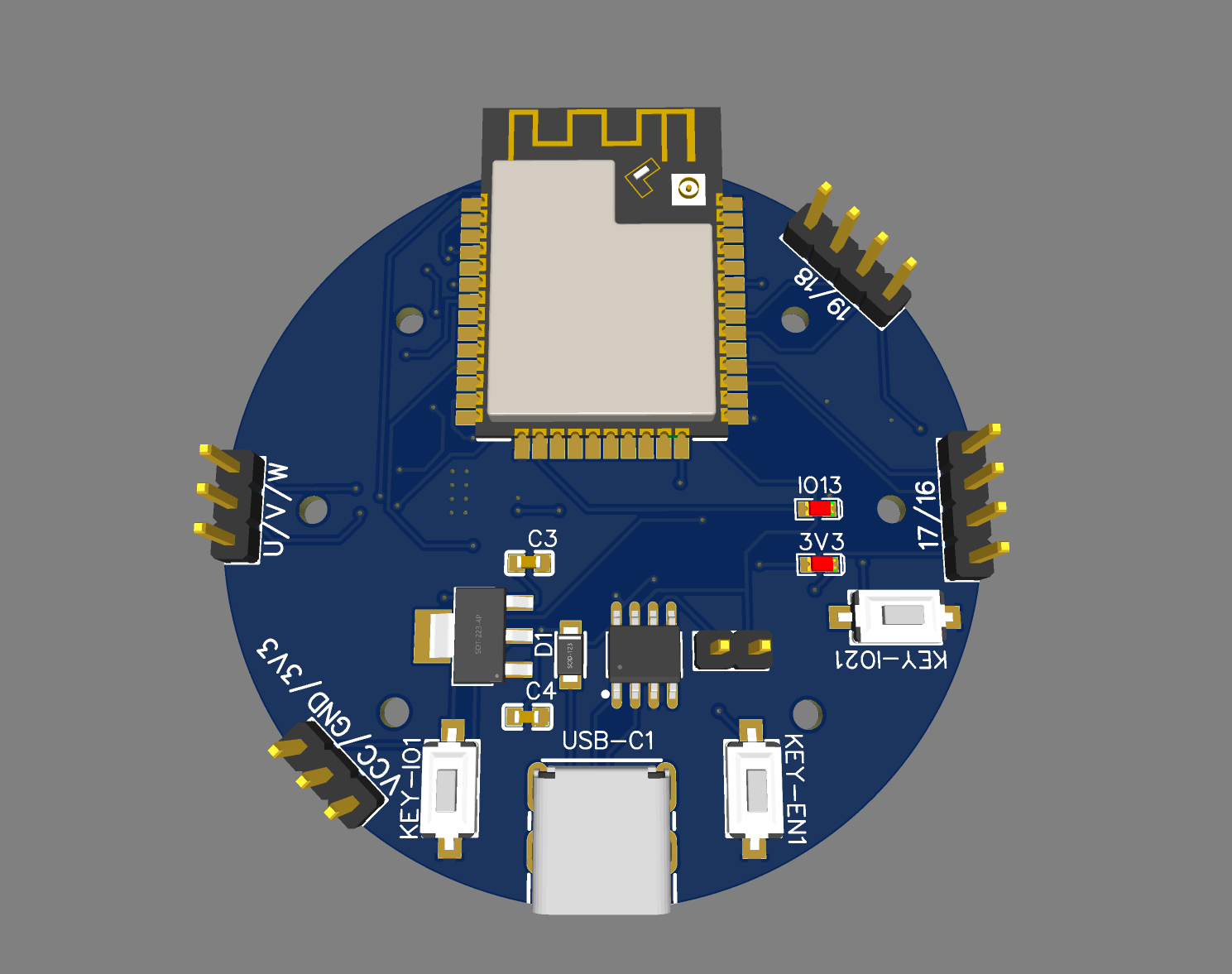
电路(PCB) 电路是基于自己设计的4010驱动板:
simplefoc程序 主控还是esp32,esp32跟atmega328p相比多了个步骤就是配置iic引脚,永远记不住怎么写,在这备份一份以后过来抄
esp32+as5600位置闭环 1 2 3 4 5 6 7 8 9 10 11 12 13 14 15 16 17 18 19 20 21 22 23 24 25 26 27 28 29 30 31 32 33 34 35 36 37 38 39 40 41 42 43 44 45 46 47 48 49 50 51 52 53 54 55 56 57 58 59 60 61 62 63 64 65 66 67 68 69 70 71 72 73 74 75 76 77 78 79 80 81 82 83 84 85 86 87 88 89 90 91 92 93 94 95 96 97 98 99 100 101 102 103 104 105 106 107 108 109 110 111 112 113 114 /** * ESP32 position motion control example with magnetic sensor */ #include <SimpleFOC.h> // SPI Magnetic sensor instance (AS5047U example) // MISO 12 // MOSI 9 // SCK 14 // magnetic sensor instance - SPI //MagneticSensorSPI sensor = MagneticSensorSPI(AS5147_SPI, 15); // I2C Magnetic sensor instance (AS5600 example) // make sure to use the pull-ups!! // SDA 21 // SCL 22 // magnetic sensor instance - I2C MagneticSensorI2C sensor = MagneticSensorI2C(AS5600_I2C); // Analog output Magnetic sensor instance (AS5600) // MagneticSensorAnalog sensor = MagneticSensorAnalog(A1, 14, 1020); // Motor instance BLDCMotor motor = BLDCMotor(11); BLDCDriver3PWM driver = BLDCDriver3PWM(25, 26, 27, 14); // angle set point variable float target_angle = 0; // instantiate the commander Commander command = Commander(Serial); void doTarget(char* cmd) { command.scalar(&target_angle, cmd); } void setup() { // initialise magnetic sensor hardware Wire.setPins(33,32); Wire.begin(); sensor.init(&Wire); // link the motor to the sensor motor.linkSensor(&sensor); // driver config // power supply voltage [V] driver.voltage_power_supply = 12; driver.init(); // link the motor and the driver motor.linkDriver(&driver); // choose FOC modulation (optional) motor.foc_modulation = FOCModulationType::SpaceVectorPWM; // set motion control loop to be used motor.controller = MotionControlType::angle; // contoller configuration // default parameters in defaults.h // velocity PI controller parameters motor.PID_velocity.P = 0.2f; motor.PID_velocity.I = 20; // maximal voltage to be set to the motor motor.voltage_limit = 6; // velocity low pass filtering time constant // the lower the less filtered motor.LPF_velocity.Tf = 0.01f; // angle P controller motor.P_angle.P = 20; // maximal velocity of the position control motor.velocity_limit = 40; // use monitoring with serial Serial.begin(115200); // comment out if not needed motor.useMonitoring(Serial); // initialize motor motor.init(); // align sensor and start FOC motor.initFOC(); // add target command T command.add('T', doTarget, "target angle"); Serial.println(F("Motor ready.")); Serial.println(F("Set the target angle using serial terminal:")); _delay(1000); } void loop() { // main FOC algorithm function // the faster you run this function the better // Arduino UNO loop ~1kHz // Bluepill loop ~10kHz motor.loopFOC(); // Motion control function // velocity, position or voltage (defined in motor.controller) // this function can be run at much lower frequency than loopFOC() function // You can also use motor.move() and set the motor.target in the code motor.move(target_angle); // function intended to be used with serial plotter to monitor motor variables // significantly slowing the execution down!!!! // motor.monitor(); // user communication command.run(); }
esp32+LM324力矩闭环(未经验证) 我在LM324周围实际焊接的电阻是1K和100K,所以实际上电压会放大101倍,就按100倍算,也就是1A时电阻产生电压为0.01V,ADC电压为1V,esp32默认ADC范围是3.3V,也就是电流可以达到3.3A已经超过驱动芯片drv8313最大值2.5A了,量程刚刚好。三相线都有电流检测功能。
这个程序还没有通过验证。
1 2 3 4 5 6 7 8 9 10 11 12 13 14 15 16 17 18 19 20 21 22 23 24 25 26 27 28 29 30 31 32 33 34 35 36 37 38 39 40 41 42 43 44 45 46 47 48 49 50 51 52 53 54 55 56 57 58 59 60 61 62 63 64 65 66 67 68 69 70 #include <SimpleFOC.h> MagneticSensorI2C sensor = MagneticSensorI2C(AS5600_I2C); BLDCMotor motor = BLDCMotor(11); BLDCDriver3PWM driver = BLDCDriver3PWM(25, 26, 27, 14); float target_voltage = 3; LowsideCurrentSense current_sense = LowsideCurrentSense(0.01f, 101.0f, 34, 39, 36); Commander command = Commander(Serial); void doTarget(char* cmd) { command.scalar(&target_voltage, cmd); } void setup() { Wire.setPins(33,32); Wire.begin(); sensor.init(&Wire); motor.linkSensor(&sensor); driver.voltage_power_supply = 12; driver.init(); motor.linkDriver(&driver); // aligning voltage motor.voltage_sensor_align = 3; current_sense.linkDriver(&driver); motor.foc_modulation = FOCModulationType::SpaceVectorPWM; motor.torque_controller = TorqueControlType::dc_current; motor.controller = MotionControlType::torque; // PID参数 - 默认 motor.PID_current_q.P = 5; // 3 - Arduino UNO/MEGA //motor.PID_current_q.I = 1000; // 300 - Arduino UNO/MEGA //motor.PID_current_q.D = 0; Serial.begin(115200); motor.useMonitoring(Serial); motor.init(); if (current_sense.init()) Serial.println("Current sense init success!"); else{ Serial.println("Current sense init failed!"); return; } motor.linkCurrentSense(¤t_sense); motor.initFOC(); current_sense.driverAlign(motor.voltage_sensor_align); command.add('T', doTarget, "target current"); Serial.println(F("Motor ready.")); Serial.println(F("Set the target current using serial terminal:")); _delay(1000); } void loop() { motor.loopFOC(); motor.move(target_voltage); command.run(); }
drv8313驱动+as5600磁编码器+ina240电流检测(验证完成,上面两个方案现在意义不大)
1 2 3 4 5 6 7 8 9 10 11 12 13 14 15 16 17 18 19 20 21 22 23 24 25 26 27 28 29 30 31 32 33 34 35 36 37 38 39 40 41 42 43 44 45 46 47 48 49 50 51 52 53 54 55 56 57 58 59 60 61 62 63 64 65 66 67 68 69 70 71 72 73 74 75 76 77 78 79 #include <SimpleFOC.h> BLDCMotor motor = BLDCMotor(7 ); BLDCDriver3PWM driver = BLDCDriver3PWM(25 , 26 , 27 , 14 ); MagneticSensorI2C sensor = MagneticSensorI2C(AS5600_I2C); InlineCurrentSense current_sense = InlineCurrentSense(0.01f , 50.0f , 34 , 35 ); Commander command = Commander(Serial); void doTarget (char * cmd) { command.scalar(&motor.target, cmd); }void setup () { sensor.init(); motor.linkSensor(&sensor); driver.voltage_power_supply = 12 ; driver.init(); motor.linkDriver(&driver); current_sense.linkDriver(&driver); current_sense.init(); motor.linkCurrentSense(¤t_sense); motor.torque_controller = TorqueControlType::foc_current; motor.controller = MotionControlType::torque; motor.PID_current_q.P = 5 ; motor.PID_current_q.I= 300 ; motor.PID_current_d.P= 5 ; motor.PID_current_d.I = 300 ; motor.LPF_current_q.Tf = 0.01 ; motor.LPF_current_d.Tf = 0.01 ; Serial.begin(115200 ); motor.useMonitoring(Serial); motor.init(); motor.initFOC(); command.add('T' , doTarget, "target current" ); Serial.println(F("Motor ready." )); Serial.println(F("Set the target current using serial terminal:" )); _delay(1000 ); } void loop () { motor.loopFOC(); motor.move(); command.run(); }

