前言 这篇文章应该很长,要写很久。我会先列一个框架然后再补充内容,如果一部分写完我就会在目录标题写上已完成,没有标注的不完整或未经确认内容仅供参考。
现在大部分内容都已经完成,就不写已完成标识了———— 2023.6.24补充
在大一的时候做一些小东西一般会用arduino,好似大家都这样做,但是后来就发现esp32是真的香,引脚众多功能齐全计算能力强自带联网,而且性价比极高,价格亲民(此处点名树莓派),唯一的缺点大概就是可能是电源导致的不稳定。众多功能也就带来了众多科技点要学,所以写这样一篇ALL IN ONE,一方面自己以后要用可以直接拿来用,也可以给初学者作为一个笔记整理甚至指导。
超级无敌基础的操作 开发板索引地址
1 https://raw.githubusercontent.com/espressif/arduino-esp32/gh-pages/package_esp32_index.json
arduino基础
1
2
3
4
5
6
7
8
9
10
11
12
13
pinMode(Pin, OUTPUT); pinMode(Pin,INPUT); pinMode(Pin,INPUT_PULLUP); digitalRead(Pin); digitalWrite(Pin, HIGH); analogRead(pin); Serial.begin(115200 ); Serial.println(val); void setup () {}void loop () {}
引脚和资源分配与使用
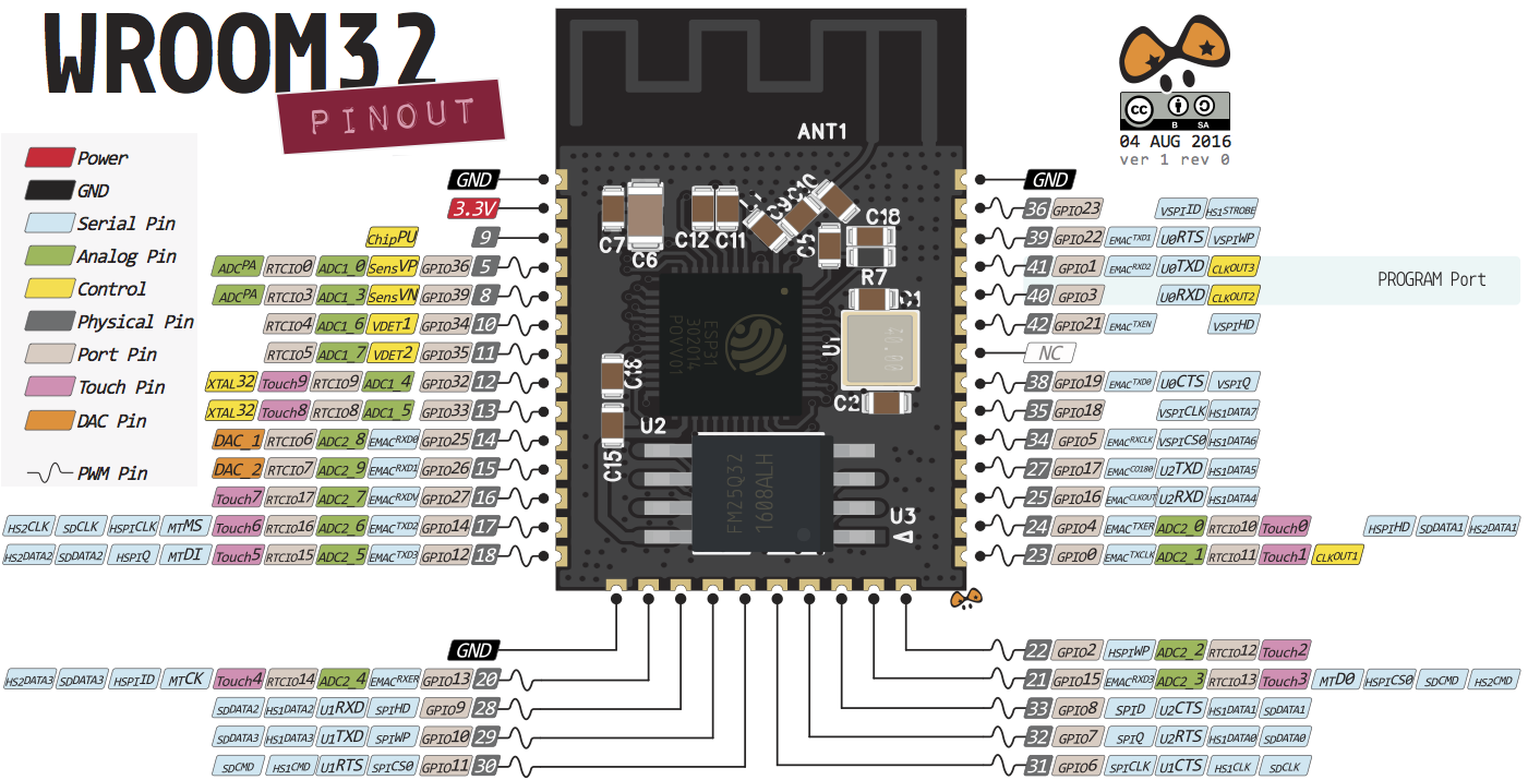
不建议使用或限制使用的引脚 不建议使用 Strapping引脚 ,SPI flash 引脚 以及 仅输入的引脚
Strapping引脚 1 2 3 4 5 6 GPIO 0 GPIO 2 GPIO 4 GPIO 5 (启动时必须为高电平) GPIO 12 (启动时必须为低电平) GPIO 15 (启动时必须为高电平)
在硬件上要注意使用外接模块时不能将GPIO12拉高,否则将导致ESP32启动异常。还有一些GPIO在启动或重置时其状态更改为高或者输出PWM信号,在使用时需要注意。
集成在ESP-WROOM-32的SPI flash引脚 GPIO 6 到 GPIO 11 在一些 ESP32 开发板中公开。但是,这些引脚连接到 ESP-WROOM-32 芯片上的集成 SPI 闪存,不推荐用于其他用途。所以,不要在你的项目中使用这些引脚:
1
2
3
4
5
6
GPIO 6 (SCK/CLK) GPIO 7 (SDO/SD0) GPIO 8 (SDI/SD1) GPIO 9 (SHD/SD2) GPIO 10 (SWP/SD3) GPIO 11 (CSC/CMD)
仅输入引脚 GPIO 34 到 39 是 GPI – 仅输入引脚。这些引脚没有内部上拉或下拉电阻。它们不能用作输出,因此只能将这些引脚用作输入:
1 2 3 4 GPIO 34 GPIO 35 GPIO 36 GPIO 39
限制使用引脚 这些引脚都是ESP32用于引导加载程序或者烧录模式/在大多数内置USB/Serial的开发板上,不需要担心这些引脚的状态,开发板会把这些引脚设置为正确的状态,以便使用烧录或启动模式。
但是,如果你有外设连接到这些引脚上,当你在尝试上传新代码、用新固件烧写ESP32或重置电路板时可能会遇到麻烦,例如不明原因的错误和失败。可能是因为这些外设阻止ESP32进入正确的模式。
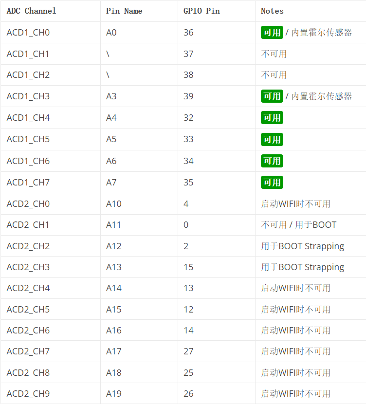
外设资源 18个ADC通道 简介 ESP32 有 18 x 12 位 ADC 输入通道(而ESP8266 只有 1x 10 位 ADC)。这些是可用作 ADC 和相应通道的 GPIO。
尽管 ESP32 有 18 个通道的 ADC,但并非所有 ADC 引脚都可供用户使用。在 8 个 ADC1 通道中,只有 6 个可用(ACD1_CH0 和 ACD1_CH3 到 ACD1_CH7),而 ADC1_CH1 和 ADC1_CH2 不可用(引脚在 ESP32 开发板中没有暴露)。当使用 ESP32 的 Wi-Fi 时,Wi-Fi Driver 使用 ADC2 Peripheral。因此,只有在未启动 Wi-Fi 驱动程序时才能使用 ADC2。即使您正在使用 ADC2(假设未使用 Wi-Fi),所有引脚也并非随时可用,因为与 ADC2 相关的一些引脚用于其他重要目的。
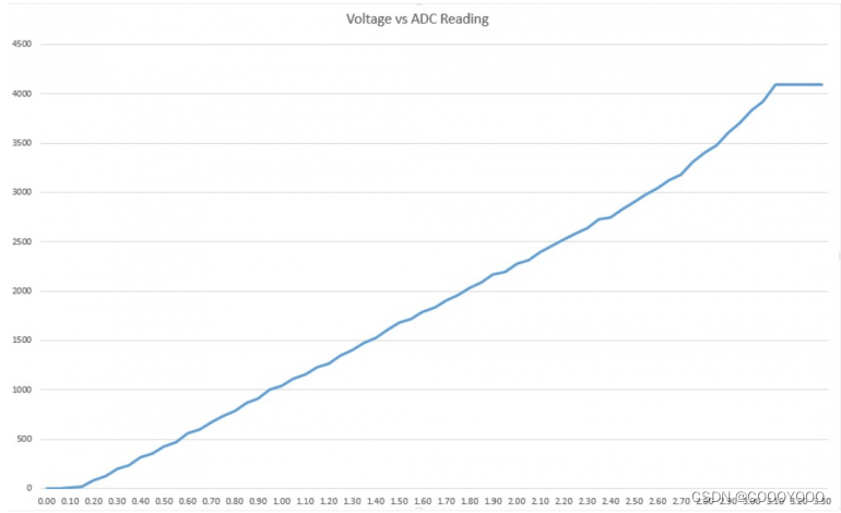
ADC 输入通道具有 12 位分辨率。这意味着您可以获得范围从 0 到 4095 的模拟读数,其中 0 对应于 0V,4095 对应于 3.3V。您还可以在代码和 ADC 范围上设置通道的分辨率。但是,ESP32 ADC 引脚没有线性行为。可能无法区分 0 和 0.1V,或 3.2 和 3.3V。
实例 读取模拟值及设置分辨率 1 2 3 4 5 6 7 8 9 10 11 void setup () { Serial.begin(115200 ); delay(500 ); } void loop () { int potValue = analogRead(34 ); Serial.println(potValue); }
读取模拟电压(毫伏) 1 2 3 4 5 6 7 void setup () { Serial.begin(115200 ); } void loop () { int analogValue=analogReadMilliVolts(34 ); Serial.println(analogValue); }
设置ADC衰减 GPIO口会对输入的电压进行一定的减弱,以防止电压过大造成单片机损坏,衰减程度越大,测量的电压范围越大.
默认参数是衰减11db,即使没有设置,也是11db.
1 2 3 4 analogSetAttenuation(attenuation) analogSetPinAttenuation(pin, attenuation)
attenuation可选值(当VDD_A为3.3V时):ADC_0db: 集没有衰减。ADC可以测量大约800mvADC_2_5db: ADC的输入电压将被衰减,扩展测量范围至约1100 mVADC_6db: ADC的输入电压将被衰减,扩展测量范围至约1350 mVADC_11db: ADC的输入电压将被衰减,扩展测量范围至约2600 mV
1 2 3 4 5 6 7 8 9 10 void setup () { Serial.begin(115200 ); analogSetPinAttenuation(2 ,ADC_11db); } void loop () { int analogValue=analogRead(2 ); Serial.println(analogValue); }
其他可设置项 1 2 3 4 5 6 7 8 9 10 11 12 analogSetCycles(cycles) analogSetSamples(samples) analogSetClockDiv(attenuation) adcAttachPin(pin) adcStart(pin) adcBusy(pin) resultadcEnd(pin)
4组SPI接口 简介 默认情况下可用的SPI的引脚映射是:
SPI
MOSI
MISO
CLK
CS
VSPI(SPI3)
GPIO 23
GPIO 19
GPIO 18
GPIO 5
HSPI(SPI2)
GPIO 13
GPIO 12
GPIO 14
GPIO 15
MISO: 主器件数据输出,从器件数据输入。
SPI0和SPI1在内部用于访问ESP32所连接的闪存。两个控制器共享相同的SPI总线信号,并且有一个仲裁器来确定哪个可以访问该总线。
SPI2和SPI3是通用SPI控制器,有时分别称为HSPI和VSPI。它们向用户开放。SPI2和SPI3具有独立的总线信号,分别具有相同的名称。每条总线具有3条CS线,最多能控制6个SPI从设备。
实例
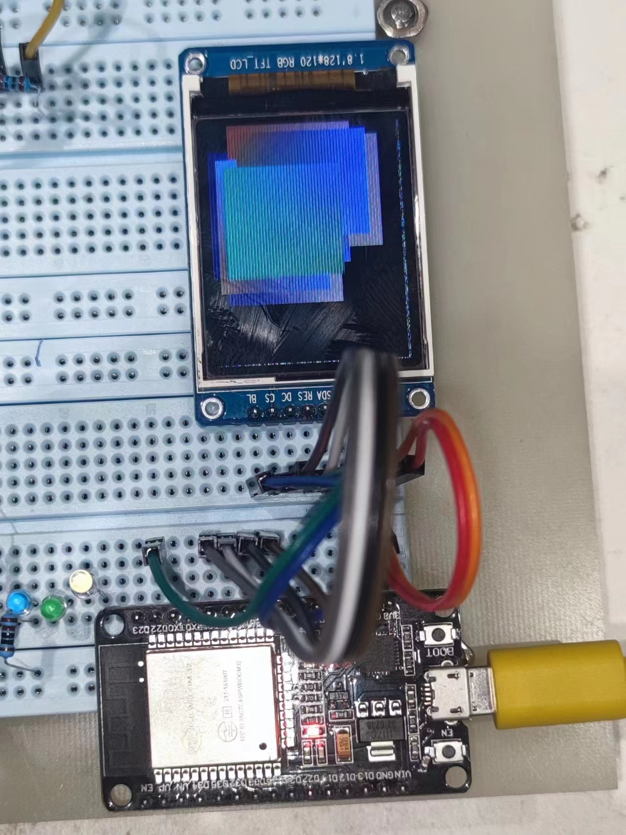
1 2 3 4 5 6 7 8 9 10 11 12 13 14 15 16 17 18 19 20 21 22 23 24 25 26 27 28 29 30 31 32 33 34 35 36 37 38 39 40 41 42 43 44 45 46 47 48 49 50 51 52 53 54 55 56 57 58 59 60 61 62 63 64 65 66 67 68 69 70 71 72 73 74 75 76 77 78 79 80 81 82 83 84 85 86 87 88 89 90 91 92 93 94 95 96 97 98 99 100 101 102 103 104 105 106 107 108 109 110 111 112 113 114 115 116 117 118 119 120 121 122 123 124 125 126 127 128 129 130 131 132 133 134 135 136 137 138 139 140 141 142 143 144 145 146 147 148 149 150 151 152 153 154 155 156 157 158 159 160 161 162 163 164 165 166 167 168 169 170 171 172 173 174 175 176 177 178 179 180 181 182 183 184 185 186 187 188 189 190 191 192 193 194 #include <SPI.h> #include "Ucglib.h" Ucglib_ST7735_18x128x160_SWSPI ucg ( 5 , 18 , 21 , 22 , 19 ) ; void setup (void ) { delay(1000 ); ucg.begin(UCG_FONT_MODE_TRANSPARENT); ucg.setColor(0 , 0 ,0 ,0 ); ucg.setColor(1 , 0 ,0 ,0 ); ucg.setColor(2 , 0 ,0 ,0 ); ucg.setColor(3 , 0 ,0 ,0 ); } uint8_t z = 127 ; uint8_t lcg_rnd (void ) { z = (uint8_t )((uint16_t )65 *(uint16_t )z + (uint16_t )17 ); return z; } void draw_text (void ) { ucg.setFont(ucg_font_ncenR14_tr); ucg.setColor(lcg_rnd(),lcg_rnd(),lcg_rnd()); ucg.setPrintPos(0 ,20 ); ucg.print("The quick brown" ); ucg.setPrintPos(0 ,40 ); ucg.print("fox jumps over" ); ucg.setPrintPos(0 ,60 ); ucg.print("the lazy dog" ); } void draw_box (void ) { ucg_int_t x, y, w, h; ucg.setColor(lcg_rnd(),lcg_rnd(),lcg_rnd()); x = lcg_rnd() & 31 ; y = lcg_rnd() & 31 ; w = 63 ; w += lcg_rnd() & 31 ; h = 63 ; h += lcg_rnd() & 31 ; ucg.drawBox(x,y,w, h); } void draw_gradient_box (void ) { ucg_int_t x, y, w, h; static uint8_t idx = 0 ; switch (idx & 3 ){ case 0 : ucg.setColor(0 , lcg_rnd(),lcg_rnd(),lcg_rnd()); break ; case 1 : ucg.setColor(1 , lcg_rnd(),lcg_rnd(),lcg_rnd()); break ; case 2 : ucg.setColor(2 , lcg_rnd(),lcg_rnd(),lcg_rnd()); break ; case 3 : ucg.setColor(3 , lcg_rnd(),lcg_rnd(),lcg_rnd()); break ; } idx++; x = lcg_rnd() & 31 ; y = lcg_rnd() & 31 ; w = 63 ; w += lcg_rnd() & 31 ; h = 63 ; h += lcg_rnd() & 31 ; ucg.drawGradientBox(x,y,w, h); } uint16_t measure (void (*draw_fn)(void )) { uint16_t FPS10 = 0 ; uint32_t time; ucg.clearScreen(); time = millis() + 10 *1000 ; do { draw_fn(); FPS10++; } while ( millis() < time ); return FPS10; } static const unsigned char u8d_tab[3 ] = { 100 , 10 , 1 } ;const char *u8dp (char * dest, uint8_t v) { uint8_t pos; uint8_t d; uint8_t c; for ( pos = 0 ; pos < 3 ; pos++ ) { d = '0' ; c = *(u8d_tab+pos); while ( v >= c ) { v -= c; d++; } dest[pos] = d; } dest[3 ] = '\0' ; return dest; } const char *u8d (uint8_t v, uint8_t d) { static char buf[8 ]; d = 3 -d; return u8dp(buf, v) + d; } const char *convert_FPS (uint16_t fps) { static char buf[6 ]; strcpy (buf, u8d( (uint8_t )(fps/10 ), 3 )); buf[3 ] = '.' ; buf[4 ] = (fps % 10 ) + '0' ; buf[5 ] = '\0' ; return buf; } void show_result (const char *s, uint16_t fps) { ucg.clearScreen(); ucg.setFont(ucg_font_helvR18_tr); ucg.setColor(255 , 255 , 255 ); ucg.setPrintPos(0 ,25 ); ucg.print(s); ucg.setPrintPos(0 ,50 ); ucg.print(convert_FPS(fps)); delay(2000 ); } void loop (void ) { show_result("Text" , measure(draw_text)); show_result("Box" , measure(draw_box)); show_result("Gradient" , measure(draw_gradient_box)); delay(500 ); }
3组UART接口 GPIO ESP32里面有3个串口,uart0默认作为log和console输出,我们可以使用uart1和uart2。因为接SPI Flash,会占用GPIO6~GPIO11,所以uart1使用默认管脚的时候会有冲突,我们需要把管脚配置到其它的GPIO上.
UART
GPIO
UART
GPIO
U0_RXD
GPIO3
U0_CTS
GPIO19
U0_TXD
GPIO1
U0_RTS
GPIO22
U1_RXD
GPIO9
U1_CTS
GPIO6
U1_TXD
GPIO10
U1_RTS
GPIO11
U2_RXD
GPIO16
U2_CTS
GPIO8
U2_TXD
GPIO17
U2_RTS
GPIO7
硬件串口重定义 1 2 3 4 5 6 7 8 9 10 11 12 #include <HardwareSerial.h> HardwareSerial SerialPort (1 ) ; void setup () { SerialPort.begin(115200 , SERIAL_8N1, 4 , 2 ); } void loop () { SerialPort.println("Hello World" ); }
使用软件串口 如果硬件串口不够用可以使用软件串口,但是效率较低
1 2 3 4 5 6 7 8 9 10 11 12 13 14 15 16 17 18 19 20 21 #include <SoftwareSerial.h> SoftwareSerial mySerial (2 , 3 ) ; void setup () { Serial.begin(115200 ); while (!Serial) { } Serial.println("Hello World!" ); mySerial.begin(9600 ); mySerial.println("Hello World?" ); } void loop () { if (mySerial.available()) Serial.write(mySerial.read()); if (Serial.available()) mySerial.write(Serial.read()); }
在arduino uno使用多个软件串口时,同一时间只能监听一个串口,不知道esp32有没有这个限制,不过需要注意这件事时候你已经用了5个串口通道了,一般人应该都没这个需求吧懒得尝试了
1组I2C接口 简介 ESP32默认的I2C引脚为:
1 2 GPIO 21 (SDA) GPIO 22 (SCL)
在ESP32中任何引脚都可以定义为SDA或SCL,但不到逼不得已不推荐这么做。
可在Arduino IDE 中使用以下语句配置其它引脚为SDA或SCL
实例 主从设备传输 Wire库方法
初始化IIC连接,并作为主机或者从机设备加入IIC总线
1 2 begin(); begin(address);
主机向从机发送数据请求信号
使用 requestFrom() 后,从机端可以使用 onRequest() 注册一个事件用以响应主机的请求;主机可以通过available() 和 read() 函数读取这些数据
1 2 Wire.requestFrom(address, quantity); Wire.requestFrom(address, quantity, stop);
设定传输数据到指定地址的从机设备
随后可以使用 write() 函数发送数据,并搭配endTransmission()函数结束数据传输
1 Wire.beginTransmission(address);
结束数据传输
1 2 Wire.endTransmission() ; Wire.endTransmission(stop);
发送数据
为主机状态时,主机将要发送的数据加入发送队列;当为从机状态时,从机发送数据至发起请求的主机
1 2 3 Wire.write(value); Wire.write(string ); Wire.write(data, length);
参数:
value,以单字节发送。
string,以一系列字节发送。
data,以字节形式发送数组。
length,传输的字节数。
byte型值,返回输入的字节数。
返回接收到的字节数
在主机中,一般用于主机发送数据请求后;在从机中,一般用于数据接收事件中。
读取1B的数据
在主机中,当使用 requestFrom() 函数发送数据请求信号后,需要使用 read() 函数来获取数据;在从机中需要使用该函数读取主机发送来的数据
从机端注册一个事件,当从机收到主机发送的数据时即被触发
1 Wire.onReceive(handler);
参数:
handler,当从机接收到数据时可被触发的事件。该事件带有一个int型参数(从主机读到的字节数)且没有返回值,如 void myHandler(int numBytes)
注册一个事件,当从机接收到主机的数据请求时即被触发
1 Wire.onRequest(handler);
参数:
handler,可被触发的事件。该事件不带参数和返回值,如 voidmyHandler()
主从收发
主发从收
主机:1 2 3 4 5 6 7 8 9 10 11 12 13 14 15 16 17 18 #include <Wire.h> void setup () { Wire.begin(); } byte x = 0 ; void loop () { Wire.beginTransmission(8 ); Wire.write("x is " ); Wire.write(x); Wire.endTransmission(); x++; delay(500 ); }
从机:1 2 3 4 5 6 7 8 9 10 11 12 13 14 15 16 17 18 19 20 21 22 23 24 #include <Wire.h> void setup () { Wire.begin(8 ); Wire.onReceive(receiveEvent); Serial.begin(9600 ); } void loop () { delay(100 ); } void receiveEvent (int howMany) { while (1 < Wire.available()) { char c = Wire.read(); Serial.print(c); } int x = Wire.read(); Serial.println(x); }
主收从发
主机:
1 2 3 4 5 6 7 8 9 10 11 12 13 14 15 16 17 18 19 #include <Wire.h> void setup () { Wire.begin(); Serial.begin(9600 ); } void loop () { Wire.requestFrom(8 , 6 ); while (Wire.available()) { char c = Wire.read(); Serial.print(c); } Serial.println(); delay(500 ); }
从机:
1 2 3 4 5 6 7 8 9 10 11 12 13 14 15 16 17 18 #include <Wire.h> void setup () { Wire.begin(8 ); Wire.onRequest(requestEvent); } void loop () { delay(100 ); } void requestEvent () { Wire.write("hello " ); }
应答交互通讯
这个程序用于iic控制电机驱动,主机是一个uno,负责发送目标速度,从机是电机驱动板,负责返回当前角度
其中电机驱动板使用了TwoWire来创建两个iic通道
uno:
1 2 3 4 5 6 7 8 9 10 11 12 13 14 15 16 17 18 19 20 21 22 23 24 25 26 27 28 29 30 31 32 #include <Wire.h> void setup () { Serial.begin(115200 ); Wire.begin(); } void loop () { String inString="" ; while (Serial.available()>0 ){ inString += char (Serial.read()); delay(1 ); } if (inString!="" ){ Serial.print("IIC send:" ); Serial.println(inString); const char * cstr = inString.c_str(); Wire.beginTransmission(1 ); Wire.write(cstr); Wire.endTransmission(); } String recString="" ; Wire.requestFrom(1 , 8 ); while (Wire.available()) { recString += char (Wire.read()); } if (recString!="" ){ Serial.print("IIC received:" ); Serial.println(recString.toInt()); } }
esp32驱动板:
1 2 3 4 5 6 7 8 9 10 11 12 13 14 15 16 17 18 19 20 21 22 23 24 25 26 27 28 29 30 31 32 33 34 35 36 37 38 39 40 41 42 43 44 45 46 47 48 49 50 51 52 53 54 55 56 57 58 59 60 61 62 63 64 65 66 67 68 69 70 71 72 #include <SimpleFOC.h> #include <Wire.h> #include <dummy.h> MagneticSensorI2C sensor = MagneticSensorI2C(AS5600_I2C); BLDCMotor motor = BLDCMotor(11 ); BLDCDriver3PWM driver = BLDCDriver3PWM(25 , 26 , 27 , 14 ); float target_velocity = 0 ;TwoWire Wire_foc = TwoWire(0 ); TwoWire Wire_rec = TwoWire(1 ); void setup () { Serial.begin(115200 ); Wire_rec.setPins(16 ,17 ); Wire_rec.begin(1 ); Wire_rec.onReceive(receiveEvent); Wire_rec.onRequest(requestEvent); Wire_foc.setPins(33 ,32 ); Wire_foc.begin(); sensor.init(&Wire_foc); motor.linkSensor(&sensor); driver.voltage_power_supply = 12 ; driver.init(); motor.linkDriver(&driver); motor.controller = MotionControlType::velocity; motor.PID_velocity.P = 0.2f ; motor.PID_velocity.I = 20 ; motor.PID_velocity.D = 0 ; motor.voltage_limit = 6 ; motor.PID_velocity.output_ramp = 1000 ; motor.LPF_velocity.Tf = 0.01f ; motor.init(); motor.initFOC(); _delay(1000 ); } void loop () { motor.loopFOC(); motor.move(target_velocity); } void receiveEvent (int howMany) { String inString="" ; for (int i=howMany;i>1 ;i--){ inString += char (Wire_rec.read()); } target_velocity = inString.toFloat()/100 ; inString="" ; } void requestEvent () { float get_ang = sensor.getAngle(); int ang = int (get_ang*100 ); Serial.println(ang); char cstr[8 ]; itoa(ang, cstr, 10 ); Wire_rec.write(cstr); }
as5600编码器 此程序为读取as5600磁编码器的i2c数据,其中SDA为D22,SCL为D23:
1 2 3 4 5 6 7 8 9 10 11 12 13 14 15 16 17 18 19 20 21 22 23 24 25 26 27 #include "AS5600.h" #include "Wire.h" AS5600 as5600; void setup () { Serial.begin(115200 ); Serial.println(__FILE__); Serial.print("AS5600_LIB_VERSION: " ); Serial.println(AS5600_LIB_VERSION); as5600.begin(22 ,23 ); as5600.setDirection(AS5600_CLOCK_WISE); int b = as5600.isConnected(); Serial.print("Connect: " ); Serial.println(b); delay(1000 ); } void loop () { Serial.println(as5600.rawAngle() * AS5600_RAW_TO_DEGREES); delay(100 ); }
oled屏幕 1 2 3 4 5 6 7 8 9 10 11 12 13 14 15 16 17 18 19 20 21 22 23 24 25 26 27 28 #include <Wire.h> #include "SSD1306.h" SSD1306 display (0x3c , 21 , 22 ) ; SSD1306 display2 (0x3c , 18 , 19 ) ; void setup () { display.init(); display.setFont(ArialMT_Plain_24); display.drawString(32 , 0 , "ctrl+v" ); display.display(); display2.init(); display2.setFont(ArialMT_Plain_24); display2.drawString(32 , 0 , "ctrl+c" ); display2.display(); } void loop () { delay(1000 ); display.clear(); display.drawString(32 , 0 , "ctrl+c" ); display.display(); delay(1000 ); display.clear(); display.drawString(32 , 0 , "ctrl+v" ); display.display(); }
16个PWM通道 简介 ESP32 PWM 控制器有 8 个高速通道(80MHz)和 8 个低速通道(1MHz),我们总共有 16 个通道。它们根据速度分为两组。每组有 4 个定时器/8 个通道。这意味着每两个通道共享同一个定时器。因此,我们无法独立控制每对通道的 PWM 频率。
实例 1 2 3 4 5 6 7 int freq = 50 ; int channel = 8 ; int resolution = 8 ; const int servo = 12 ; ledcSetup(channel, freq, resolution); ledcAttachPin(servo, channel); ledcWrite(channel, 127 );
顺便赠送一个使用舵机的函数
1 2 3 4 5 6 7 8 9 10 11 int servoPWM (int degree) { const float deadZone = 6.4 ; const float max = 32 ; if (degree < 60 ) degree = 60 ; if (degree > 120 ) degree = 120 ; return (int )(((max - deadZone) / 180 ) * degree + deadZone); }
2个DAC 简介 ESP32 上有 2 x 8 位 DAC 通道,用于将数字信号转换为模拟电压信号输出。这些是 DAC 通道:
1 2 DAC1 (GPIO25) DAC2 (GPIO26)
实例 输出电压将在0-3.3V之间变化:
1 2 3 4 5 6 7 8 9 10 11 12 void setup () {} void loop () { for (int dutyCycle = 0 ; dutyCycle <= 255 ; dutyCycle = dutyCycle + 1 ){ dacWrite(25 , dutyCycle); delay(50 ); } for (int dutyCycle = 255 ; dutyCycle >= 0 ; dutyCycle = dutyCycle - 1 ){ dacWrite(25 , dutyCycle); delay(50 ); } }
10个电容感应GPIO 简介 ESP32 有 10 个内部电容式触摸传感器。它们可以感知任何带电荷的物体的变化,比如人体皮肤。因此,他们可以检测用手指触摸 GPIO 时引起的变化。这些引脚可以集成到电容式焊盘中并取代机械按钮。电容式触控引脚还可用于将 ESP32 从深度睡眠中唤醒
这些内部触摸传感器连接到这些 GPIO:
1 2 3 4 5 6 7 8 9 10 T0 (GPIO 4) T1 (GPIO 0) T2 (GPIO 2) T3 (GPIO 15) T4 (GPIO 13) T5 (GPIO 12) T6 (GPIO 14) T7 (GPIO 27) T8 (GPIO 33) T9 (GPIO 32)
实例 1 2 3 4 5 6 7 8 9 10 11 12 13 14 15 16 17 18 19 20 21 22 23 24 const int touchPin = 4 ;const int threshold = 20 ;int touchValue;void setup () { Serial.begin(115200 ); delay(1000 ); } void loop () { touchValue = touchRead(touchPin); Serial.print(touchValue); if (touchValue < threshold){ Serial.println("on" ); } else { Serial.println("off" ); } delay(500 ); }
中断 简介 所有引脚都可以配置为中断。
中断函数:
1 attachInterrupt(digitalPinToInterrupt(GPIO), function, mode);
其中参数mode有5种:
LOW:每当引脚为LOW时触发中断;HIGH:每当引脚为高电平时触发中断;CHANGE:每当引脚值发生变化时触发中断——例如从高电平变为低电平或从低电平变为高电平;FALLING:当引脚从高电平变为低电平时;RISING: 当引脚从低电平变为高电平时触发。
实例 外部引脚中断
此处内容在2023.10.30进行了修改
程序目的是在引脚上升沿输出开机毫秒数
有个小问题就是如果在中断函数使用串口输出极易导致中断看门狗复位,因此应该在中断函数中只进行计时并保存,串口输出交给loop循环
这是错误的程序:
1 2 3 4 5 6 7 8 9 10 11 12 13 14 15 16 17 18 19 20 21 22 23 24 25 26 27 28 29 unsigned long t;struct Button { const uint8_t PIN; uint32_t numberKeyPresses; bool pressed; }; Button button1 = {18 , 0 , false }; void IRAM_ATTR isr () { button1.numberKeyPresses++; button1.pressed = true ; t = micros(); Serial.println(t); } void setup () { Serial.begin(115200 ); pinMode(button1.PIN, INPUT_PULLUP); attachInterrupt(button1.PIN, isr, FALLING); } void loop () { if (button1.pressed) { Serial.printf ("Button has been pressed %u times\n" , button1.numberKeyPresses); button1.pressed = false ; } }
具体报错如下:
1 2 3 4 5 6 7 8 9 10 11 12 13 14 15 16 17 18 19 20 21 22 23 17:24:50.601 -> Guru Meditation Error: Core 1 panic'ed (Interrupt wdt timeout on CPU1). 17:24:50.601 -> 17:24:50.601 -> Core 1 register dump: 17:24:50.642 -> PC : 0x4008ab8a PS : 0x00060b35 A0 : 0x80089b02 A1 : 0x3ffbf0ec 17:24:50.642 -> A2 : 0x3ffb8314 A3 : 0x3ffb81a4 A4 : 0x00000004 A5 : 0x00060b23 17:24:50.642 -> A6 : 0x00060b23 A7 : 0x00000001 A8 : 0x3ffb81a4 A9 : 0x00000018 17:24:50.642 -> A10 : 0x3ffb81a4 A11 : 0x00000018 A12 : 0x3ffc22fc A13 : 0x00060b23 17:24:50.642 -> A14 : 0x007bf308 A15 : 0x003fffff SAR : 0x0000000e EXCCAUSE: 0x00000006 17:24:50.667 -> EXCVADDR: 0x00000000 LBEG : 0x400863fd LEND : 0x4008640d LCOUNT : 0xfffffffd 17:24:50.667 -> Core 1 was running in ISR context: 17:24:50.667 -> EPC1 : 0x400da62f EPC2 : 0x00000000 EPC3 : 0x00000000 EPC4 : 0x00000000 17:24:50.667 -> 17:24:50.667 -> 17:24:50.667 -> Backtrace: 0x4008ab87:0x3ffbf0ec |<-CORRUPTED 17:24:50.667 -> 17:24:50.667 -> 17:24:50.667 -> Core 0 register dump: 17:24:50.667 -> PC : 0x4008ad27 PS : 0x00060035 A0 : 0x8008972b A1 : 0x3ffbea2c 17:24:50.700 -> A2 : 0x3ffbf308 A3 : 0xb33fffff A4 : 0x0000abab A5 : 0x00060023 17:24:50.700 -> A6 : 0x00060021 A7 : 0x0000cdcd A8 : 0x0000abab A9 : 0xffffffff 17:24:50.700 -> A10 : 0x3ffc2118 A11 : 0x00000000 A12 : 0x3ffc2114 A13 : 0x00000007 17:24:50.700 -> A14 : 0x007bf308 A15 : 0x003fffff SAR : 0x0000001d EXCCAUSE: 0x00000006
应该改成这样:
1 2 3 4 5 6 7 8 9 10 11 12 13 14 15 16 17 18 19 20 21 22 23 24 25 26 27 28 29 unsigned long t;struct Button { const uint8_t PIN; uint32_t numberKeyPresses; bool pressed; }; Button button1 = {18 , 0 , false }; void IRAM_ATTR isr () { button1.numberKeyPresses++; button1.pressed = true ; t = micros(); } void setup () { Serial.begin(115200 ); pinMode(button1.PIN, INPUT_PULLUP); attachInterrupt(button1.PIN, isr, FALLING); } void loop () { if (button1.pressed) { Serial.printf ("Button has been pressed %u times\n" , button1.numberKeyPresses); button1.pressed = false ; Serial.println(t); } }
还有要注意的就是time不能作为变量名否则报错,在这件事情上折腾好久没想起来time居然是个函数这件事
定时器中断 定时器每秒触发一次中断
1 2 3 4 5 6 7 8 9 10 11 12 13 14 15 16 17 18 19 20 hw_timer_t *timer = NULL ;void IRAM_ATTR InterruptEvent () { Serial.println("BEEP" ); } void setup () { Serial.begin(115200 ); timer = timerBegin(0 , 80 , true ); timerAttachInterrupt(timer, &InterruptEvent, true ); timerAlarmWrite(timer, 1000000 , true ); timerAlarmEnable(timer); } void loop () {}
不常用内容 2个I2S:高速数位音讯传输标准协议 在ESP32引脚上实际是标记为 DAC1 和 DAC2
16个RTC的GPIO ESP32 上有 RTC GPIO 支持。当 ESP32 处于深度睡眠时,可以使用路由到 RTC 低功耗子系统的 GPIO。当超低功耗 (ULP) 协处理器运行时,这些 RTC GPIO 可用于将 ESP32 从深度睡眠中唤醒。以下 GPIO 可用作外部唤醒源
1 2 3 4 5 6 7 8 9 10 11 12 13 14 15 16 RTC_GPIO0 (GPIO36) RTC_GPIO3 (GPIO39) RTC_GPIO4 (GPIO34) RTC_GPIO5 (GPIO35) RTC_GPIO6 (GPIO25) RTC_GPIO7 (GPIO26) RTC_GPIO8 (GPIO33) RTC_GPIO9 (GPIO32) RTC_GPIO10 (GPIO4) RTC_GPIO11 (GPIO0) RTC_GPIO12 (GPIO2) RTC_GPIO13 (GPIO15) RTC_GPIO14 (GPIO13) RTC_GPIO15 (GPIO12) RTC_GPIO16 (GPIO14) RTC_GPIO17 (GPIO27)
内置2个霍尔传感器 内置霍尔效应传感器,可检测周围磁场的变化。
1 2 GPIO 36 (VP) GPIO 39 (VN)
使能EN 3.3V 稳压器的启用引脚。它被拉高,因此接地以禁用 3.3V 稳压器。这意味着可以使用连接到按钮的此引脚来重新启动 ESP32。
GPIO电流 根据 ESP32 数据表中的“推荐操作条件”部分,每个 GPIO 的绝对最大电流消耗为 40mA。
软件应用 技术栈 按钮消抖 上面的代码经常用于读取按钮是否被按下,但是实际上机械按钮在开关时总会因为各种原因导致的抖动,导致多次触发中断。
我解决这个问题的想法就是先检查最近50ms有没有过中断,如果没有,继续检查接下来20ms有没有回到高电平,如果还没有,就可以判定确实按下了按钮。代码如下:
1 2 3 4 5 6 7 8 9 10 11 12 13 14 15 16 17 18 19 20 21 22 23 24 25 26 unsigned long previousMillis = 0 ;void setup () { Serial.begin(115200 ); pinMode(12 , INPUT|PULLUP ); attachInterrupt(12 , blink, FALLING); } void loop () {}void blink () { int ding = 1 ; unsigned long currentMillis = millis(); if (currentMillis - previousMillis > 50 ){ while (millis() - currentMillis < 20 ){ if (digitalRead(12 )==1 ){ ding = 0 ; break ; } } if (ding){ previousMillis = currentMillis; Serial.println("interrupt" ); } } }
光污染制作–ws2812驱动 讲真这个和ESP32关系不大,但是我就想写怎么着hhh
1 2 3 4 5 6 7 8 9 10 11 12 13 14 15 16 17 18 19 20 21 22 #include "Freenove_WS2812_Lib_for_ESP32.h" #define LEDS_COUNT 128 #define LEDS_PIN 13 #define CHANNEL 0 Freenove_ESP32_WS2812 strip = Freenove_ESP32_WS2812(LEDS_COUNT, LEDS_PIN, CHANNEL, TYPE_GRB); void setup () { strip.begin(); } void loop () { for (int j = 0 ; j < 255 ; j += 2 ) { for (int i = 0 ; i < LEDS_COUNT; i++) { strip.setLedColorData(i, strip.Wheel((i * 256 / LEDS_COUNT + j) & 255 )); } strip.show(); delay(5 ); } }
WIFI连接服务器获取数据 此处示例为使用STA模式连接WIFI并发起TCP连接获取数据,然后读取其中的r和d作为分隔符的内容
1 2 3 4 5 6 7 8 9 10 11 12 13 14 15 16 17 18 19 20 21 22 23 24 25 26 27 28 29 30 31 32 33 34 35 36 37 38 39 40 41 42 43 44 45 #include <WiFi.h> const char *ssid = "xxx" ;const char *password = "xxx" ;const IPAddress serverIP (0 ,0 ,0 ,0 ) ;uint16_t serverPort = 23333 ;WiFiClient client; void setup () { Serial.begin(115200 ); Serial.println(); WiFi.mode(WIFI_STA); WiFi.setSleep(false ); WiFi.setHostname("esp32" ); WiFi.begin(ssid, password); while (WiFi.status() != WL_CONNECTED){ delay(2000 ); Serial.print("." ); } Serial.println("WiFi connected, IP address: " ); Serial.println(WiFi.localIP()); } void loop () { Serial.println("connecting to server" ); if (client.connect(serverIP, serverPort)){ Serial.println("connected" ); while (client.connected() || client.available()){ if (client.available()){ String d = client.readStringUntil('d' ); Serial.println(d); dir = d.toInt(); String r = client.readStringUntil('r' ); run = r.toInt(); Serial.println(r); } } }else { Serial.println("err" ); client.stop(); } delay(5000 ); }
蓝牙键盘 D12引脚拉低则蓝牙键盘输出HELLO。问题在于如果esp32重启,必须重新配对才能让蓝牙键盘继续工作,还不知道原因,网上也没有搜到类似现象,也许是我esp32板子的问题?等我再换一个板子试一试。好了问题解决,github直接下载的0.3版本的ESP32-BLE-Keyboard库有bug,已经有人提出了issue ,在0.3.2中已经解决了这个问题,不过0.3.2还是Pre-release。下载这个库时候记得看版本要0.3.2。
1 2 3 4 5 6 7 8 9 10 11 12 13 14 15 16 17 18 19 20 21 22 23 24 25 26 27 28 29 30 31 32 33 34 #include <BleKeyboard.h> unsigned long previousMillis = 0 ;BleKeyboard bleKeyboard ("ESP32" ,"triority" ,100 ) ; void setup () { Serial.begin(115200 ); pinMode(12 , INPUT|PULLUP ); attachInterrupt(12 , blink, FALLING); bleKeyboard.begin(); } void loop () {} void blink () { int ding = 1 ; unsigned long currentMillis = millis(); if (currentMillis - previousMillis > 80 ){ while (millis() - currentMillis < 30 ){ if (digitalRead(12 )==1 ){ ding = 0 ; break ; } } if (ding){ previousMillis = currentMillis; Serial.println("interrupt" ); if (bleKeyboard.isConnected()){ bleKeyboard.print("HELLO" ); Serial.println("HELLO" ); } } } }
ESP32 NOW:一对一单向通信 这部分内容来自lingshunlab
简介 ESP-NOW 是乐鑫开发的一种无连接通信协议,沒有握手协议(CHAP),具有短包传输的特点。该协议使多个设备能够在不使用Wi-Fi的情况下以简单的方式进行相互通讯,类似于低功耗 2.4GHz 无线连接,设备之间的配对是在它们通信之前就需要配对好在代码中。配对完成后,连接是安全的,持久的,点对点的。换句话说,如果你的一块ESP32板突然断电或重置,当它重新启动时,它就会自动连接到它的已经提前配对好的网路中以继续通信。
限制 在有限的加密对等点:
Station模式最多支持10个设备的加密对等点网络通讯;
SoftAP或SoftAP+Station模式下最多支持6个设备;
多个未加密对等点:
其总数应少于 20 个设备
有效载荷限制为 250 字节。
2个ESP32开发板在空旷区域中进行单向通讯,相隔30米仍然能很好低接收信息。
示例 发送端(slave/sender) 1 2 3 4 5 6 7 8 9 10 11 12 13 14 15 16 17 18 19 20 21 22 23 24 25 26 27 28 29 30 31 32 33 34 35 36 37 38 39 40 41 42 43 44 45 46 47 48 49 50 51 52 53 54 55 56 57 58 59 60 61 62 63 64 65 66 67 68 69 70 71 72 73 74 75 76 77 #include <esp_now.h> #include <WiFi.h> uint8_t broadcastAddress[] = {0xFF , 0xFF , 0xFF , 0xFF , 0xFF , 0xFF };typedef struct struct_message { char a[40 ]; int b; float c; bool d; } struct_message; struct_message myData; esp_now_peer_info_t peerInfo;void OnDataSent (const uint8_t *mac_addr, esp_now_send_status_t status) { Serial.print("\r\nLast Packet Send Status:\t" ); Serial.println(status == ESP_NOW_SEND_SUCCESS ? "Delivery Success" : "Delivery Fail" ); } void setup () { Serial.begin(115200 ); WiFi.mode(WIFI_STA); if (esp_now_init() != ESP_OK) { Serial.println("Error initializing ESP-NOW" ); return ; } esp_now_register_send_cb(OnDataSent); memcpy (peerInfo.peer_addr, broadcastAddress, 6 ); peerInfo.channel = 0 ; peerInfo.encrypt = false ; if (esp_now_add_peer(&peerInfo) != ESP_OK){ Serial.println("Failed to add peer" ); return ; } } void loop () { strcpy (myData.a, "Welcome to Lingshunlab.com" ); myData.b = random(1 ,20 ); myData.c = 1.2 ; myData.d = false ; esp_err_t result = esp_now_send(broadcastAddress, (uint8_t *) &myData, sizeof (myData)); if (result == ESP_OK) { Serial.println("Sent with success" ); } else { Serial.println("Error sending the data" ); } delay(2000 ); }
ESPNOW接收端 1 2 3 4 5 6 7 8 9 10 11 12 13 14 15 16 17 18 19 20 21 22 23 24 25 26 27 28 29 30 31 32 33 34 35 36 37 38 39 40 41 42 43 44 45 46 47 48 49 50 51 52 53 54 #include <esp_now.h> #include <WiFi.h> typedef struct struct_message { char a[40 ]; int b; float c; bool d; } struct_message; struct_message myData; void OnDataRecv (const uint8_t * mac, const uint8_t *incomingData, int len) { memcpy (&myData, incomingData, sizeof (myData)); Serial.print("Bytes received: " ); Serial.println(len); Serial.print("Char: " ); Serial.println(myData.a); Serial.print("Int: " ); Serial.println(myData.b); Serial.print("Float: " ); Serial.println(myData.c); Serial.print("Bool: " ); Serial.println(myData.d); Serial.println(); } void setup () { Serial.begin(115200 ); WiFi.mode(WIFI_STA); if (esp_now_init() != ESP_OK) { Serial.println("Error initializing ESP-NOW" ); return ; } esp_now_register_recv_cb(OnDataRecv); } void loop () {}
EEPROM:断电数据保存 EEPROM (electrically erasable programmable read-only memory)是一种用户可修改的ROM,又或者称为闪存(Flash Memory)。是一种非易失性ROM,可以擦除和重新编程单个字节的数据。这就是 EEPROM芯片被称为字节可擦除芯片的原因。EEPROM 通常用于在计算和其他电子设备中存储少量数据。
EEPROM里面的数据是可以断电保存的,重新上电数据并不会丢失。但是,闪存的一个限制是可刷写数据的次数。你可以根据需要多次从闪存中读取数据,但大多数设备闪存的写入次数设计为大约 100,000 到 1,000,000 次写入操作。
Arduino Uno 的EEEROM大小为1024个字节。
在 ESP32 的闪存读取和写入将使用 EEPROM 库。其实是和 Arduino EEPROM 一样的,并没有太大区别。
1 2 3 4 5 6 7 8 9 10 11 12 13 14 15 16 17 18 19 20 21 22 23 24 25 #include <EEPROM.h> #define EEPROM_SIZE 1 int read_value = 0 ;void setup () { Serial.begin(115200 ); EEPROM.begin(EEPROM_SIZE); } void loop () { read_value = EEPROM.read(0 ); Serial.println(read_value); read_value++; EEPROM.write(0 , read_value); EEPROM.commit(); delay(1000 ); }
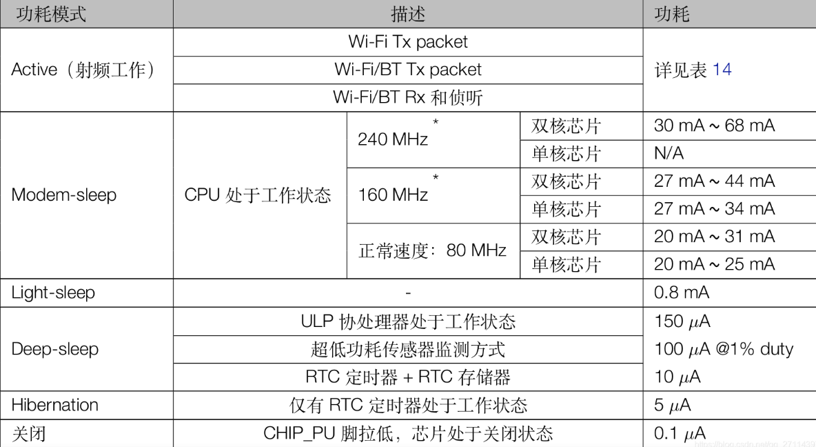
低功耗 低功耗模式
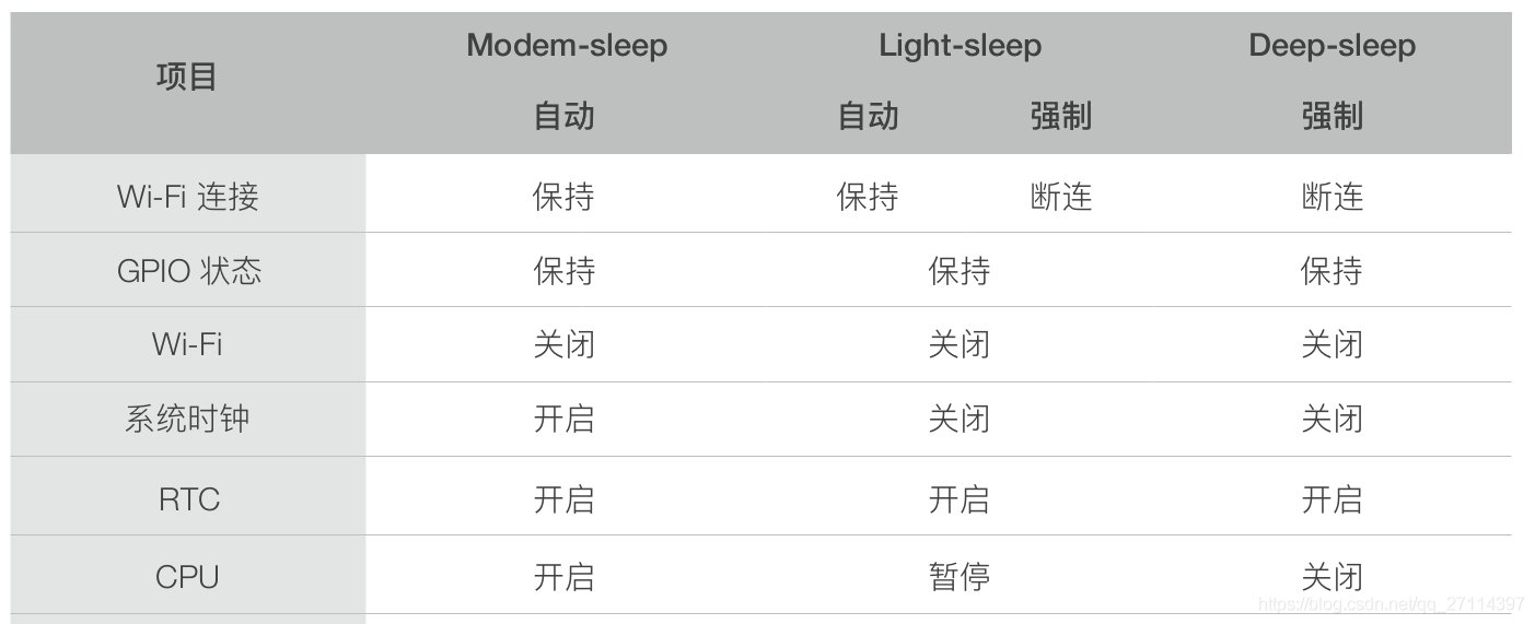
Modem-sleep 模式:CPU 可运行,时钟可被配置。Wi-Fi/蓝牙基带和射频关闭Light-sleep 模式:CPU 暂停运行,Wi-Fi/蓝牙基带和射频关闭。RTC 存储器和外设以及 ULP 协处理器运行。任何唤醒事件(MAC、主机、RTC 定时器或外部中断)都会唤醒芯片Deep-sleep 模式:CPU 和大部分外设都会掉电,Wi-Fi/蓝牙基带和射频关闭,只有 RTC 存储器和 RTC 外设以及 ULP 协处理器可以工作。Wi-Fi 和蓝牙连接数据存储在 RTC 中
Modem-sleep 目前 ESP32 的Modem-sleep仅工作在Station模式下,连接路由器后生效。Station会周期性在工作状态和睡眠状态两者之间切换。DTIM Beacon机制与路由器保持连接。在Modem-sleep模式下,系统可以自动被唤醒,无需配置唤醒源
在 Modem-sleep 模式下,ESP32 会在两次 DTIM Beacon 间隔时间内,关闭 Wi-Fi 模块电路,达到省电效果,在下次 Beacon 到来前自动唤醒。睡眠时间由路由器的 DTIM Beacon 时间决定。Modem-sleep 模式可以保持与路由器的 Wi-Fi 连接,并通过路由器接收来自手机或者服务器的交互信息
Modem-sleep 一般用于 CPU 持续处于工作状态并需要保持 Wi-Fi 连接的应用场景,例如,使用 ESP32 本地语音唤醒功能,CPU 需要持续采集和处理音频数据。
一般路由器的 DTIM Beacon 间隔为 100 ms ~ 1,000 ms
Light-sleep Light-sleep的工作模式与Modem-sleep相似,不同的是,除了关闭 Wi-Fi 模块电路以外,在 Light-sleep 模式下,还会关闭时钟并暂停内部 CPU,比Modem-sleep功耗更低。有两种方式使 CPU 进入Light-sleep模式:
强制Light-sleep: 通过调用 API 强制 CPU 进入 Light-sleep 模式,强制进入 Light-sleep 模式后,不能通过路由器接收来自手机或者服务器的交互信息。强制关闭 Wi-Fi 模块电路并暂停内部 CPU。能通过定时器、 GPIO(RTC IO 和 Digital IO)和 UART 唤醒。从 Light-sleep 唤醒后,会从进入休眠的位置继续执行程序。
自动Light-sleep: 配置为自动休眠方式后,会在 CPU 处于空闲的状态下自动进入Light-sleep模式,能通过路由器接收来自手机或者服务器的交互信息。通常自动Light-sleep会与Modem-sleep 模式以及电源管理功能共同使用,电源管理功能允许系统根据 CPU 负载动态调节 CPU 频率以降低功耗。比如 Wi-Fi 开关的应用,大部分时间 CPU 都是空闲的,直到收到控制命令,CPU 才需要进行 GPIO 的操作。
强制 Light-sleep 接口调用后,并不会立即休眠,而是等到系统空闲后才进入休眠
若系统应用中有小于 DTIM Beacon 间隔时间的循环定时,系统将不能进入 Light-sleep 模式
Deep-sleep 相对于其他两种模式,系统无法自动进入Deep-sleep,需要由用户调用接口函数esp_deep_sleep_start()进入Deep-sleep模式。在该模式下,芯片会断开所有 Wi-Fi 连接与数据连接,进入Deep-sleep模式,只有 RTC 存储器和 RTC 外设以及 ULP 协处理器可以工作。从Deep-sleep唤醒后,CPU 将软件复位重启
Deep-sleep可以用于低功耗的传感器应用,或者大部分时间都不需要进行数据传输的情况。设备可以每隔一段时间从Deep-sleep状态醒来测量数据并上传,之后继续进入Deep-sleep。也可以将多个数据存储于RTC memory(RTC memory在Deep-sleep模式下仍然可以保存数据),然后一次发送出去
定时唤醒:6uA左右 这是官方提供的示例代码,已经把注释改成了中文。
1 2 3 4 5 6 7 8 9 10 11 12 13 14 15 16 17 18 19 20 21 22 23 24 25 26 27 28 29 30 31 32 33 34 #define uS_TO_S_FACTOR 1000000ULL #define TIME_TO_SLEEP 5 RTC_DATA_ATTR int bootCount = 0 ; void print_wakeup_reason () { esp_sleep_wakeup_cause_t wakeup_reason; wakeup_reason = esp_sleep_get_wakeup_cause(); switch (wakeup_reason){ case ESP_SLEEP_WAKEUP_EXT0 : Serial.println("Wakeup caused by external signal using RTC_IO" ); break ; case ESP_SLEEP_WAKEUP_EXT1 : Serial.println("Wakeup caused by external signal using RTC_CNTL" ); break ; case ESP_SLEEP_WAKEUP_TIMER : Serial.println("Wakeup caused by timer" ); break ; case ESP_SLEEP_WAKEUP_TOUCHPAD : Serial.println("Wakeup caused by touchpad" ); break ; case ESP_SLEEP_WAKEUP_ULP : Serial.println("Wakeup caused by ULP program" ); break ; default : Serial.printf ("Wakeup was not caused by deep sleep: %d\n" ,wakeup_reason); break ; } } void setup () { Serial.begin(115200 ); delay(1000 ); ++bootCount; Serial.println("Boot number: " + String(bootCount)); print_wakeup_reason(); esp_sleep_enable_timer_wakeup(TIME_TO_SLEEP * uS_TO_S_FACTOR); Serial.println("Setup ESP32 to sleep for every " + String(TIME_TO_SLEEP) + " Seconds" ); Serial.println("Going to sleep now" ); Serial.flush(); esp_deep_sleep_start(); Serial.println("This will never be printed" ); } void loop () {}
Touchpad唤醒:36uA左右 调用esp_deep_sleep_enable_touchpad_wakeup()函数使能touchpad唤醒,然后调用esp_deep_sleep_start()函数进入Deep-sleep模式
1 2 3 4 5 6 7 8 9 10 11 12 13 14 15 16 17 18 19 20 21 22 23 24 25 26 27 28 29 30 31 32 33 34 35 36 37 38 39 40 41 42 43 44 45 46 47 48 49 50 51 52 53 54 55 56 57 58 59 60 61 62 63 64 65 66 67 68 69 70 71 72 73 74 75 76 77 78 79 80 81 82 83 84 #if CONFIG_IDF_TARGET_ESP32 #define THRESHOLD 40 #else #define THRESHOLD 5000 #endif RTC_DATA_ATTR int bootCount = 0 ; touch_pad_t touchPin;void print_wakeup_reason () { esp_sleep_wakeup_cause_t wakeup_reason; wakeup_reason = esp_sleep_get_wakeup_cause(); switch (wakeup_reason){ case ESP_SLEEP_WAKEUP_EXT0 : Serial.println("Wakeup caused by external signal using RTC_IO" ); break ; case ESP_SLEEP_WAKEUP_EXT1 : Serial.println("Wakeup caused by external signal using RTC_CNTL" ); break ; case ESP_SLEEP_WAKEUP_TIMER : Serial.println("Wakeup caused by timer" ); break ; case ESP_SLEEP_WAKEUP_TOUCHPAD : Serial.println("Wakeup caused by touchpad" ); break ; case ESP_SLEEP_WAKEUP_ULP : Serial.println("Wakeup caused by ULP program" ); break ; default : Serial.printf ("Wakeup was not caused by deep sleep: %d\n" ,wakeup_reason); break ; } } void print_wakeup_touchpad () { touchPin = esp_sleep_get_touchpad_wakeup_status(); #if CONFIG_IDF_TARGET_ESP32 switch (touchPin){ case 0 : Serial.println("Touch detected on GPIO 4" ); break ; case 1 : Serial.println("Touch detected on GPIO 0" ); break ; case 2 : Serial.println("Touch detected on GPIO 2" ); break ; case 3 : Serial.println("Touch detected on GPIO 15" ); break ; case 4 : Serial.println("Touch detected on GPIO 13" ); break ; case 5 : Serial.println("Touch detected on GPIO 12" ); break ; case 6 : Serial.println("Touch detected on GPIO 14" ); break ; case 7 : Serial.println("Touch detected on GPIO 27" ); break ; case 8 : Serial.println("Touch detected on GPIO 33" ); break ; case 9 : Serial.println("Touch detected on GPIO 32" ); break ; default : Serial.println("Wakeup not by touchpad" ); break ; } #else if (touchPin < TOUCH_PAD_MAX){ Serial.printf ("Touch detected on GPIO %d\n" , touchPin); } else { Serial.println("Wakeup not by touchpad" ); } #endif } void setup () { Serial.begin(115200 ); delay(1000 ); ++bootCount; Serial.println("Boot number: " + String(bootCount)); print_wakeup_reason(); print_wakeup_touchpad(); #if CONFIG_IDF_TARGET_ESP32 touchSleepWakeUpEnable(T3,THRESHOLD); touchSleepWakeUpEnable(T7,THRESHOLD); #else touchSleepWakeUpEnable(T3,THRESHOLD); #endif Serial.println("Going to sleep now" ); esp_deep_sleep_start(); Serial.println("This will never be printed" ); } void loop () {}
GPIO唤醒:6uA左右
RTC IO模块包含当其中一个RTC IO的电平为唤醒电平(可配置为逻辑高或低)触发唤醒的逻辑。RTC IO是 RTC 外设电源域的一部分,因此如果使能该唤醒源,RTC 外设将在睡眠期间保持上电状态。在 ESP32 的修订版 0 和 1 中,此唤醒源与 ULP 和触摸唤醒源不兼容。
由于在此模式下启用了RTC IO模块,因此也可以使用内部上拉或下拉电阻。esp_sleep_enable_ext0_wakeup()函数可用于启用此唤醒源。
RTC 控制器包含使用 多个 RTC IO 触发唤醒的逻辑。两个逻辑功能之一可用于触发唤醒:ESP_EXT1_WAKEUP_ANY_HIGH)ESP_EXT1_WAKEUP_ALL_LOW)
但是,如果 RTC 外设断电,内部上拉和下拉电阻将被禁用。要使用内部上拉或下拉电阻,请在睡眠期间请求 RTC 外设电源域保持上电。esp_sleep_enable_ext1_wakeup()函数可用于启用此唤醒源。
1 2 3 4 5 6 7 8 9 10 11 12 13 14 15 16 17 18 19 20 21 22 23 24 25 26 27 28 29 30 31 32 33 34 35 36 37 38 39 40 41 #define BUTTON_PIN_BITMASK 0x200000000 RTC_DATA_ATTR int bootCount = 0 ; void print_wakeup_reason () { esp_sleep_wakeup_cause_t wakeup_reason; wakeup_reason = esp_sleep_get_wakeup_cause(); switch (wakeup_reason){ case ESP_SLEEP_WAKEUP_EXT0 : Serial.println("Wakeup caused by external signal using RTC_IO" ); break ; case ESP_SLEEP_WAKEUP_EXT1 : Serial.println("Wakeup caused by external signal using RTC_CNTL" ); break ; case ESP_SLEEP_WAKEUP_TIMER : Serial.println("Wakeup caused by timer" ); break ; case ESP_SLEEP_WAKEUP_TOUCHPAD : Serial.println("Wakeup caused by touchpad" ); break ; case ESP_SLEEP_WAKEUP_ULP : Serial.println("Wakeup caused by ULP program" ); break ; default : Serial.printf ("Wakeup was not caused by deep sleep: %d\n" ,wakeup_reason); break ; } } void setup () { Serial.begin(115200 ); delay(1000 ); ++bootCount; Serial.println("Boot number: " + String(bootCount)); print_wakeup_reason(); esp_sleep_enable_ext0_wakeup(GPIO_NUM_33,1 ); Serial.println("Going to sleep now" ); esp_deep_sleep_start(); Serial.println("This will never be printed" ); } void loop () {}
web服务器 连接wifi后,浏览器输入串口输出的ip,打开网页就会让led灯亮起一秒。考虑到学弟喜欢写脚本疯狂访问来让继电器输出PWM,加了个10s的延时不接受新的连接。
1 2 3 4 5 6 7 8 9 10 11 12 13 14 15 16 17 18 19 20 21 22 23 24 25 26 27 28 29 30 31 32 33 34 35 36 37 38 39 40 #include <WiFi.h> #include <WebServer.h> const char * ssid = "xxx" ;const char * password = "xxx" ;int led0=13 ;WebServer server (80 ) ; void handleRoot () { String HTML = "<!DOCTYPE html>\ <html><head><meta charset='utf-8'></head>\ <body>没错,这就是ESP32网页!\ </body></html>" ; digitalWrite(led0, 0 ); server.send(200 , "text/html" , HTML); delay(3000 ); digitalWrite(led0, 1 ); delay(10000 ); } void setup () { Serial.begin(115200 ); pinMode(led0, OUTPUT); digitalWrite(led0, 1 ); WiFi.mode(WIFI_STA); WiFi.begin(ssid, password); Serial.println("开始连接WIFI" ); while (WiFi.status() != WL_CONNECTED){ Serial.print("." ); delay(100 ); } Serial.print("\nIP位址:" ); Serial.println(WiFi.localIP()); server.on("/" , handleRoot); server.onNotFound([](){ server.send(404 , "text/plain" , "File NOT found!" ); }); server.begin(); Serial.println("启动成功" ); } void loop () { server.handleClient(); }
ota升级 在Arduino IDE中选择File>Example>ArduinoOTA>OTAWebUpdate例子程序。在程序中更改成自己的WiFi名字和密码。
上载程序后打开串口监视器,按ESP32板子的复位重启按钮,通过串口监视器可以看到这个ESP32服务器的地址
输入ESP32 IP地址,可以在浏览器中输入用户名和密码,点击login。
用Sketch>Export compiled Binary。这时在sketch中创建一个.bin的文件。现在,在OTA的web page中选择文件,‘Choose File’ 按钮,选择.bin文件。点击Update按钮。开始上载程序
实操程序无法运行,未找到原因找到再来写,不过话说这个好似是一次性的,也就没太大用
多核操作 ESP32具有两个32位Tensilica Xtensa LX6微处理器,这使其成为功能强大的双核(core0和core1)微控制器。有单核和双核两种版本。但是双核版本更受欢迎,因为它们之间没有明显的价格差异。
一般使用Arduino IDE进行编程时,由于Core0已编程用于RF通信,因此代码仅在Core1上运行。我们将展示如何使用ESP32的两个内核同时执行两项操作
ESP32开发板已经安装了FreeRTOS固件。 FreeRTOS是开源的实时操作系统,在多任务处理中非常有用。 RTOS有助于管理资源并最大程度地提高系统性能。 FreeRTOS具有许多用于不同目的的API函数,使用这些API,我们可以创建任务并使它们运行在不同的内核上。
FreeRTOS API的完整文档
查找ESP32内核ID 可以从void setup()和void loop()函数中调用此函数,以了解运行这些函数的内核ID
测试一下这个程序:
1 2 3 4 5 6 7 8 9 void setup () { Serial.begin(115200 ); Serial.print("setup() function running on core: " ); Serial.println(xPortGetCoreID()); } void loop () { Serial.print("loop() function running on core: " ); Serial.println(xPortGetCoreID()); }
串口输出:
1 2 3 4 16:19:10.291 -> setup() function running on core: 1 16:19:10.291 -> loop() function running on core: 1 16:19:10.291 -> loop() function running on core: 1 16:19:10.291 -> loop() function running on core: 1
双核编程方法 Arduino IDE支持在ESP32运行FreeRTOS,而FreeRTOS API允许我们创建可以在两个内核上独立运行的任务。
创建任务 1 xTaskCreatePinnedToCore()
此函数使用7个参数:
实现任务的函数名称:task1
任务的任何名称:task1
分配给任务的堆栈大小:以字为单位
任务输入参数:可以为NULL
任务的优先级:0是最低优先级
任务句柄:可以为NULL
任务将运行的内核ID:0或1
举例:通过在xTaskCreatePinnedToCore()函数中提供所有参数来创建任务
1 xTaskCreatePinnedToCore(Task1code, "Task1", 10000, NULL, 1, NULL, 0);
定义Taskcode函数 在void setup(){}函数之外,为任务创建单独的函数,这个函数将在core0上运行
1 2 3 4 5 6 7 8 9 10 Void Task1code ( void * parameter) { Serial.print("Task1 running on core " ); Serial.println(xPortGetCoreID()); for (;;) { digitalWrite(led, HIGH); delay(500 ); digitalWrite(led, LOW); delay(500 ); } }
我们已经知道loop()和setup()函数在core1上运行,因此可以在void loop()函数中实现core1任务
喂狗 需要注意一件事,如果把一个在cpu0持续执行的任务的优先级写的大于0,那么其他任务都将无法得到cpu0,比如IDLE,而这个任务默认开启5s的看门狗,这将导致单片机每五秒重置一次,串口输出如下:
1 2 3 4 5 6 7 8 9 10 11 12 13 14 15 16 17 18 18:51:12.378 -> E (10179) task_wdt: Task watchdog got triggered. The following tasks did not reset the watchdog in time: 18:51:12.378 -> E (10179) task_wdt: - IDLE (CPU 0) 18:51:12.378 -> E (10179) task_wdt: Tasks currently running: 18:51:12.378 -> E (10179) task_wdt: CPU 0: Task1 18:51:12.378 -> E (10179) task_wdt: CPU 1: IDLE 18:51:12.378 -> E (10179) task_wdt: Aborting. 18:51:12.378 -> 18:51:12.378 -> abort() was called at PC 0x400df979 on core 0 18:51:12.378 -> 18:51:12.378 -> 18:51:12.378 -> Backtrace: 0x40083931:0x3ffbed5c |<-CORRUPTED 18:51:12.414 -> 18:51:12.414 -> 18:51:12.414 -> 18:51:12.414 -> 18:51:12.414 -> ELF file SHA256: 291ef283067b9aa7 18:51:12.414 -> 18:51:12.493 -> Rebooting...
解决方法有两个,要么让这个任务暂停给出其他任务一定的cpu时间,要么把优先级改为0,我这里就直接把优先级改成0了
示例:cpu0刷新tft屏幕,cpu1使用simplefoc控制无刷电机 其中,tft屏幕任务代码来自#include "Ucglib.h"的示例程序,foc控制任务代码来自#include <SimpleFOC.h>的示例程序
虽然但是,就这两个任务而言,其实就算都在cpu1执行也无所谓hhh
1 2 3 4 5 6 7 8 9 10 11 12 13 14 15 16 17 18 19 20 21 22 23 24 25 26 27 28 29 30 31 32 33 34 35 36 37 38 39 40 41 42 43 44 45 46 47 48 49 50 51 52 53 54 55 56 57 58 59 60 61 62 63 64 65 66 67 68 69 70 71 72 73 74 75 76 77 78 79 80 81 82 83 84 85 86 87 88 89 90 91 92 93 94 95 96 97 98 99 100 101 102 103 104 105 106 107 108 109 110 111 112 113 114 115 116 117 118 119 120 121 122 123 124 125 126 127 128 129 130 131 132 133 134 135 136 137 138 139 140 141 142 143 144 145 146 147 148 149 150 151 152 153 154 155 156 157 158 159 160 161 162 163 164 165 166 167 #include <SimpleFOC.h> #include <SPI.h> #include "Ucglib.h" #include <soc/soc.h> #include <soc/rtc_cntl_reg.h> #include "esp_task_wdt.h" Ucglib_ST7735_18x128x160_SWSPI ucg ( 19 , 18 , 16 , 17 , 5 ) ; MagneticSensorI2C sensor = MagneticSensorI2C(AS5600_I2C); BLDCMotor motor = BLDCMotor(11 ); BLDCDriver3PWM driver = BLDCDriver3PWM(25 , 26 , 27 , 14 ); float target_angle = 0 ;Commander command = Commander(Serial); void doTarget (char * cmd) { command.scalar(&target_angle, cmd); }void setup () { xTaskCreatePinnedToCore(Task1code, "Task1" , 10000 , NULL , 0 , NULL , 0 ); ucg.begin(UCG_FONT_MODE_TRANSPARENT); ucg.setColor(0 , 0 ,0 ,0 ); ucg.setColor(1 , 0 ,0 ,0 ); ucg.setColor(2 , 0 ,0 ,0 ); ucg.setColor(3 , 0 ,0 ,0 ); sensor.init(); motor.linkSensor(&sensor); driver.voltage_power_supply = 12 ; driver.init(); motor.linkDriver(&driver); motor.foc_modulation = FOCModulationType::SpaceVectorPWM; motor.controller = MotionControlType::angle; motor.PID_velocity.P = 0.2f ; motor.PID_velocity.I = 20 ; motor.voltage_limit = 5 ; motor.LPF_velocity.Tf = 0.01f ; motor.P_angle.P = 20 ; motor.velocity_limit = 40 ; Serial.begin(115200 ); motor.useMonitoring(Serial); motor.init(); motor.initFOC(); command.add('T' , doTarget, "target angle" ); Serial.println(F("Motor ready." )); Serial.println(F("Set the target angle using serial terminal:" )); _delay(1000 ); } uint8_t z = 127 ;uint8_t lcg_rnd (void ) { z = (uint8_t )((uint16_t )65 *(uint16_t )z + (uint16_t )17 ); return z; } void draw_text (void ) { ucg.setFont(ucg_font_ncenR14_tr); ucg.setColor(lcg_rnd(),lcg_rnd(),lcg_rnd()); ucg.setPrintPos(0 ,20 ); ucg.print("The quick brown" ); ucg.setPrintPos(0 ,40 ); ucg.print("fox jumps over" ); ucg.setPrintPos(0 ,60 ); ucg.print("the lazy dog" ); } void draw_box (void ) { ucg_int_t x, y, w, h; ucg.setColor(lcg_rnd(),lcg_rnd(),lcg_rnd()); x = lcg_rnd() & 31 ; y = lcg_rnd() & 31 ; w = 63 ; w += lcg_rnd() & 31 ; h = 63 ; h += lcg_rnd() & 31 ; ucg.drawBox(x,y,w, h); } void draw_gradient_box (void ) { ucg_int_t x, y, w, h; static uint8_t idx = 0 ; switch (idx & 3 ){ case 0 : ucg.setColor(0 , lcg_rnd(),lcg_rnd(),lcg_rnd()); break ; case 1 : ucg.setColor(1 , lcg_rnd(),lcg_rnd(),lcg_rnd()); break ; case 2 : ucg.setColor(2 , lcg_rnd(),lcg_rnd(),lcg_rnd()); break ; case 3 : ucg.setColor(3 , lcg_rnd(),lcg_rnd(),lcg_rnd()); break ; } idx++; x = lcg_rnd() & 31 ; y = lcg_rnd() & 31 ; w = 63 ; w += lcg_rnd() & 31 ; h = 63 ; h += lcg_rnd() & 31 ; ucg.drawGradientBox(x,y,w, h); } uint16_t measure (void (*draw_fn)(void )) { uint16_t FPS10 = 0 ; uint32_t time; ucg.clearScreen(); time = millis() + 10 *1000 ; do { draw_fn(); FPS10++; } while ( millis() < time ); return FPS10; } static const unsigned char u8d_tab[3 ] = { 100 , 10 , 1 } ;const char *u8dp (char * dest, uint8_t v) { uint8_t pos; uint8_t d; uint8_t c; for ( pos = 0 ; pos < 3 ; pos++ ) { d = '0' ; c = *(u8d_tab+pos); while ( v >= c ) { v -= c; d++; } dest[pos] = d; } dest[3 ] = '\0' ; return dest; } const char *u8d (uint8_t v, uint8_t d) { static char buf[8 ]; d = 3 -d; return u8dp(buf, v) + d; } const char *convert_FPS (uint16_t fps) { static char buf[6 ]; strcpy (buf, u8d( (uint8_t )(fps/10 ), 3 )); buf[3 ] = '.' ; buf[4 ] = (fps % 10 ) + '0' ; buf[5 ] = '\0' ; return buf; } void show_result (const char *s, uint16_t fps) { ucg.clearScreen(); ucg.setFont(ucg_font_helvR18_tr); ucg.setColor(255 , 255 , 255 ); ucg.setPrintPos(0 ,25 ); ucg.print(s); ucg.setPrintPos(0 ,50 ); ucg.print(convert_FPS(fps)); delay(2000 ); } void Task1code (void * parameter) { Serial.print("Task1 running on core " ); Serial.println(xPortGetCoreID()); while (true ){ vTaskDelay(10 ); show_result("Text" , measure(draw_text)); show_result("Box" , measure(draw_box)); show_result("Gradient" , measure(draw_gradient_box)); delay(500 ); } } void loop () { motor.loopFOC(); motor.move(target_angle); command.run(); }
复杂应用 无线配网 这个其实工作量挺大的,直接抄别人抄的了
代码 主程序
main.ino
1 2 3 4 5 6 7 8 9 10 11 12 13 14 15 16 17 18 19 20 21 22 23 24 25 26 27 28 29 30 31 #include "WiFiUser.h" const int resetPin = 0 ; int connectTimeOut_s = 15 ; void setup () { pinMode(resetPin, INPUT_PULLUP); Serial.begin(115200 ); LEDinit(); connectToWiFi(connectTimeOut_s); } void loop () { if (!digitalRead(resetPin)) { delay(5000 ); if (!digitalRead(resetPin)) { Serial.println("\n按键已长按5秒,正在清空网络连保存接信息." ); restoreWiFi(); ESP.restart(); Serial.println("已重启设备." ); } } checkDNS_HTTP(); checkConnect(true ); delay(30 ); }
库头文件
WiFiUser.h
1 2 3 4 5 6 7 8 9 10 11 12 13 14 15 16 17 18 19 20 21 22 23 24 25 26 27 28 29 30 31 32 #ifndef __WIFIUSER_H__ #define __WIFIUSER_H__ #include <WiFi.h> #include <DNSServer.h> #include <WebServer.h> #include <ESPmDNS.h> #include <esp_wifi.h> extern const int LED; extern const char * HOST_NAME; extern int connectTimeOut_s; void checkConnect (bool reConnect) ; void restoreWiFi () ; void LEDinit () ; void checkDNS_HTTP () ; void connectToWiFi (int timeOut_s) ; void handleRoot () ; void handleConfigWifi () ; void handleNotFound () ; void initSoftAP () ; void initDNS () ; void initWebServer () ; bool scanWiFi () ; void wifiConfig () ; void blinkLED (int led, int n, int t) ; #endif
库文件
WiFiUser.cpp
这个程序原作者写了`WiFi.hostname(HOST_NAME);`实测报错,注释掉也不影响使用
1 2 3 4 5 6 7 8 9 10 11 12 13 14 15 16 17 18 19 20 21 22 23 24 25 26 27 28 29 30 31 32 33 34 35 36 37 38 39 40 41 42 43 44 45 46 47 48 49 50 51 52 53 54 55 56 57 58 59 60 61 62 63 64 65 66 67 68 69 70 71 72 73 74 75 76 77 78 79 80 81 82 83 84 85 86 87 88 89 90 91 92 93 94 95 96 97 98 99 100 101 102 103 104 105 106 107 108 109 110 111 112 113 114 115 116 117 118 119 120 121 122 123 124 125 126 127 128 129 130 131 132 133 134 135 136 137 138 139 140 141 142 143 144 145 146 147 148 149 150 151 152 153 154 155 156 157 158 159 160 161 162 163 164 165 166 167 168 169 170 171 172 173 174 175 176 177 178 179 180 181 182 183 184 185 186 187 188 189 190 191 192 193 194 195 196 197 198 199 200 201 202 203 204 205 206 207 208 209 210 211 212 213 214 215 216 217 218 219 220 221 222 223 224 225 226 227 228 229 230 231 232 233 234 235 236 237 238 239 240 241 242 243 244 245 246 247 248 249 250 251 252 253 254 255 256 257 258 259 260 261 262 263 264 265 266 267 268 269 270 271 272 273 274 275 276 277 278 279 280 281 282 283 284 285 286 287 288 289 290 291 292 293 294 295 296 297 298 299 300 301 302 303 304 305 306 307 308 309 310 311 312 313 #include "WiFiUser.h" const byte DNS_PORT = 53 ; const int webPort = 80 ; const char * AP_SSID = "ESP32-4_1" ; const char * HOST_NAME = "MY_ESP32" ; String scanNetworksID = "" ; IPAddress apIP (192 , 168 , 4 , 1 ) ; String wifi_ssid = "" ; String wifi_pass = "" ; const int LED = 2 ; DNSServer dnsServer; WebServer server (webPort) ; #define ROOT_HTML "<!DOCTYPE html><html><head><title>WIFI</title><meta name=\"viewport\" content=\"width=device-width, initial-scale=1\"></head><style type=\"text/css\">.input{display: block; margin-top: 10px;}.input span{width: 100px; float: left; float: left; height: 36px; line-height: 36px;}.input input{height: 30px;width: 200px;}.btn{width: 120px; height: 35px; background-color: #000000; border:0px; color:#ffffff; margin-top:15px; margin-left:100px;}</style><body><form method=\"POST\" action=\"configwifi\"><label class=\"input\"><span>WiFi SSID</span><input type=\"text\" name=\"ssid\" value=\"\"></label><label class=\"input\"><span>WiFi PASS</span> <input type=\"text\" name=\"pass\"></label><input class=\"btn\" type=\"submit\" name=\"submit\" value=\"Submie\"> <p><span> Nearby wifi:</P></form>" void handleRoot () { if (server.hasArg("selectSSID" )) { server.send(200 , "text/html" , ROOT_HTML + scanNetworksID + "</body></html>" ); } else { server.send(200 , "text/html" , ROOT_HTML + scanNetworksID + "</body></html>" ); } } void handleConfigWifi () { if (server.hasArg("ssid" )) { Serial.print("got ssid:" ); wifi_ssid = server.arg("ssid" ); Serial.println(wifi_ssid); } else { Serial.println("error, not found ssid" ); server.send(200 , "text/html" , "<meta charset='UTF-8'>error, not found ssid" ); return ; } if (server.hasArg("pass" )) { Serial.print("got password:" ); wifi_pass = server.arg("pass" ); Serial.println(wifi_pass); } else { Serial.println("error, not found password" ); server.send(200 , "text/html" , "<meta charset='UTF-8'>error, not found password" ); return ; } server.send(200 , "text/html" , "<meta charset='UTF-8'>SSID:" + wifi_ssid + "<br />password:" + wifi_pass + "<br />已取得WiFi信息,正在尝试连接,请手动关闭此页面。" ); delay(2000 ); WiFi.softAPdisconnect(true ); server.close(); WiFi.softAPdisconnect(); Serial.println("WiFi Connect SSID:" + wifi_ssid + " PASS:" + wifi_pass); if (WiFi.status() != WL_CONNECTED) { Serial.println("开始调用连接函数connectToWiFi().." ); connectToWiFi(connectTimeOut_s); } else { Serial.println("提交的配置信息自动连接成功.." ); } } void handleNotFound () { handleRoot(); } void initSoftAP () { WiFi.mode(WIFI_AP); WiFi.softAPConfig(apIP, apIP, IPAddress(255 , 255 , 255 , 0 )); if (WiFi.softAP(AP_SSID)) { Serial.println("ESP-32S SoftAP is right." ); Serial.print("Soft-AP IP address = " ); Serial.println(WiFi.softAPIP()); Serial.println(String("MAC address = " ) + WiFi.softAPmacAddress().c_str()); } else { Serial.println("WiFiAP Failed" ); delay(1000 ); Serial.println("restart now..." ); ESP.restart(); } } void initDNS () { if (dnsServer.start(DNS_PORT, "*" , apIP)) { Serial.println("start dnsserver success." ); } else { Serial.println("start dnsserver failed." ); } } void initWebServer () { if (MDNS.begin("esp32" )) { Serial.println("MDNS responder started" ); } server.on("/" , HTTP_GET, handleRoot); server.on("/configwifi" , HTTP_POST, handleConfigWifi); server.onNotFound(handleNotFound); server.begin(); Serial.println("WebServer started!" ); } bool scanWiFi () { Serial.println("scan start" ); Serial.println("--------->" ); int n = WiFi.scanNetworks(); Serial.println("scan done" ); if (n == 0 ) { Serial.println("no networks found" ); scanNetworksID = "no networks found" ; return false ; } else { Serial.print(n); Serial.println(" networks found" ); for (int i = 0 ; i < n; ++i) { Serial.print(i + 1 ); Serial.print(": " ); Serial.print(WiFi.SSID(i)); Serial.print(" (" ); Serial.print(WiFi.RSSI(i)); Serial.print(")" ); Serial.println((WiFi.encryptionType(i) == WIFI_AUTH_OPEN) ? " " : "*" ); scanNetworksID += "<P>" + WiFi.SSID(i) + "</P>" ; delay(10 ); } return true ; } } void connectToWiFi (int timeOut_s) { Serial.println("进入connectToWiFi()函数" ); WiFi.mode(WIFI_STA); WiFi.setAutoConnect(true ); if (wifi_ssid != "" ) { Serial.println("用web配置信息连接." ); WiFi.begin(wifi_ssid.c_str(), wifi_pass.c_str()); wifi_ssid = "" ; wifi_pass = "" ; } else { Serial.println("用nvs保存的信息连接." ); WiFi.begin(); } int Connect_time = 0 ; while (WiFi.status() != WL_CONNECTED) { Serial.print("." ); digitalWrite(LED, !digitalRead(LED)); delay(500 ); Connect_time ++; if (Connect_time > 2 * timeOut_s) { digitalWrite(LED, LOW); Serial.println("" ); Serial.println("WIFI autoconnect fail, start AP for webconfig now..." ); wifiConfig(); return ; } } if (WiFi.status() == WL_CONNECTED) { Serial.println("WIFI connect Success" ); Serial.printf ("SSID:%s" , WiFi.SSID().c_str()); Serial.printf (", PSW:%s\r\n" , WiFi.psk().c_str()); Serial.print("LocalIP:" ); Serial.print(WiFi.localIP()); Serial.print(" ,GateIP:" ); Serial.println(WiFi.gatewayIP()); Serial.print("WIFI status is:" ); Serial.print(WiFi.status()); digitalWrite(LED, HIGH); server.stop(); } } void wifiConfig () { initSoftAP(); initDNS(); initWebServer(); scanWiFi(); } void restoreWiFi () { delay(500 ); esp_wifi_restore(); Serial.println("连接信息已清空,准备重启设备.." ); delay(10 ); blinkLED(LED, 5 , 500 ); digitalWrite(LED, LOW); } void checkConnect (bool reConnect) { if (WiFi.status() != WL_CONNECTED) { if (digitalRead(LED) != LOW) digitalWrite(LED, LOW); if (reConnect == true && WiFi.getMode() != WIFI_AP && WiFi.getMode() != WIFI_AP_STA ) { Serial.println("WIFI未连接." ); Serial.println("WiFi Mode:" ); Serial.println(WiFi.getMode()); Serial.println("正在连接WiFi..." ); connectToWiFi(connectTimeOut_s); } } else if (digitalRead(LED) != HIGH) digitalWrite(LED, HIGH); } void blinkLED (int led, int n, int t) { for (int i = 0 ; i < 2 * n; i++) { digitalWrite(led, !digitalRead(led)); delay(t); } } void LEDinit () { pinMode(LED, OUTPUT); digitalWrite(LED, LOW); } void checkDNS_HTTP () { dnsServer.processNextRequest(); server.handleClient(); }
使用及解析
设备热点配网(Soft AP):
ESP32配置为AP模式
手机or电脑连接ESP32热点,发送WiFi和密码
ESP32设置为STA模式
LED显示配网状态:
LED闪烁:表示正在尝试连接网络
LED常亮:表示网络连接成功
LED常灭:表示等待配网
LED闪烁5次:表示已清除wifi信息
配网界面HTML原代码
1 2 3 4 5 6 7 8 9 10 11 12 13 14 15 16 17 18 19 20 21 22 23 24 25 26 27 28 29 30 31 32 33 34 35 36 37 <!DOCTYPE html> <html> <head> <title>WIFI </title> <meta name="viewport" content="width=device-width, initial-scale=1"> </head> <style type="text/css"> .input{display: block; margin-top: 10px;} .input span{width: 100px; float: left; float: left; height: 36px; line-height: 36px;} .input input{height: 30px;width: 200px;} .btn{width: 120px; height: 35px; background-color: #000000; border:0px; color:#ffffff; margin-top:15px; margin-left:100px;} </style> <body> <form method="POST" action="configwifi"> <label class="input"> <span> WiFi SSID </span> <input type="text" name="ssid"> </label> <label class="input"> <span> WiFi PASS </span> <input type="text" name="pass"> </label> <input class="btn" type="submit" name="submit" value="Submie"> <p> <span> Nearby wifi: </P> </form> </body> </html>
硬件设计(开发板制作) 官方文档
ESP32 WROOM 32E 技术规格书
ESP32 硬件设计指南
注意事项和启动配置 模块电源电压为3.3V,一般使用AMS1117-3.3为其供电,其中要注意EN引脚要使用RC电路延迟启动。使用引脚 GPIO0 和 GPIO2 配置启动方式:
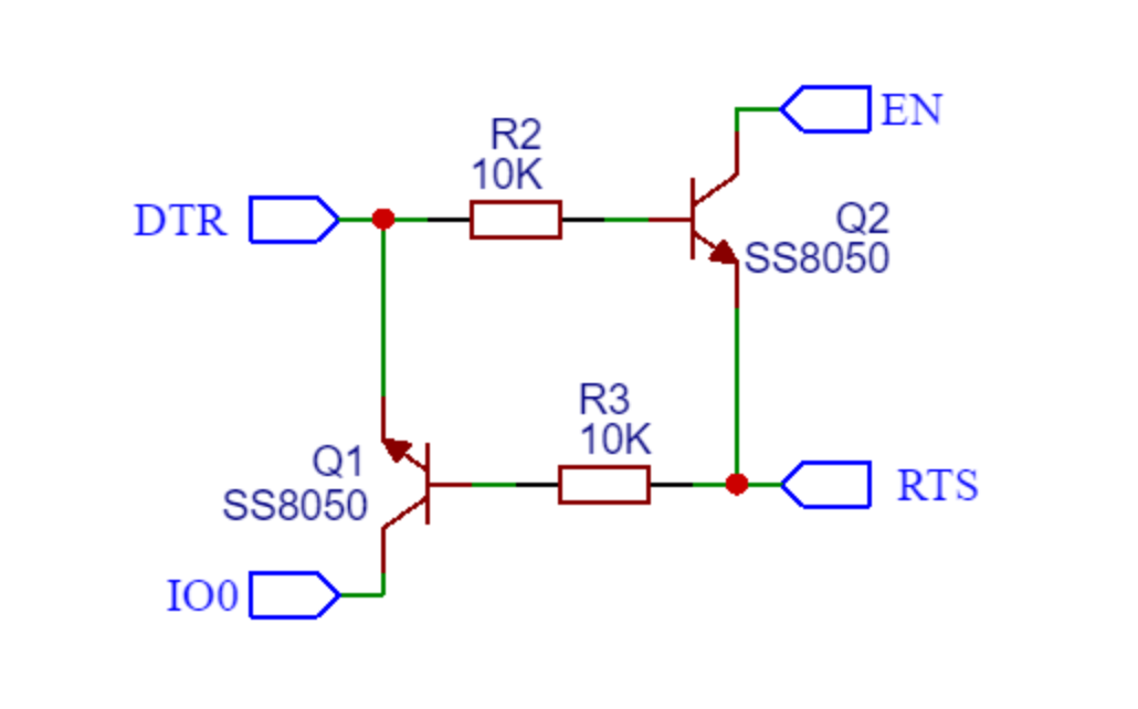
GPIO2要常态为低电平。当EN引脚处于上升沿时,GPIO0高电平进入SPI启动模式,低电平进入串口下载模式。
自动下载电路能调整boot和en脚的电平变化来满足下载时序,这是一个常用的自动下载电路原理图:
因为自动下载电路不能工作,我自己设计的电路都是直接手动按按钮来配置引脚电平设置芯片启动方式。开发板默认EN拉高,IO2拉低,IO0拉高。直接上电即可进入spi启动模式运行flash的程序,如果上电使用按钮将EN拉低和IO0拉低,IO2依然默认拉低,然后停止下拉EN启动芯片即可进入下载模式。
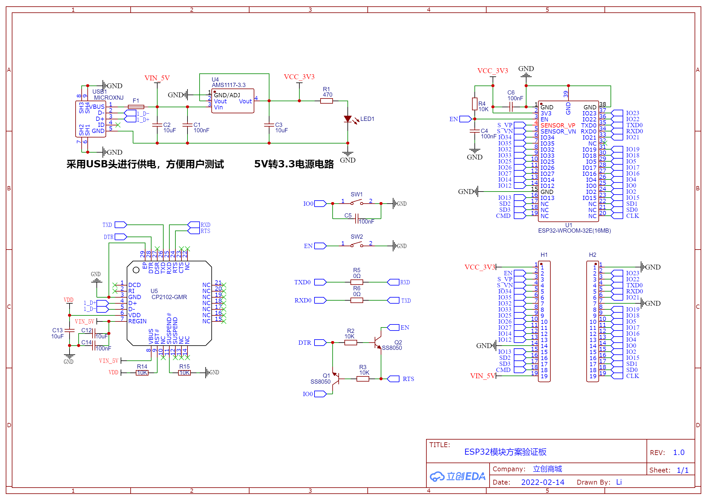
示例原理图 这是嘉立创的esp32开发板的方案验证板 :
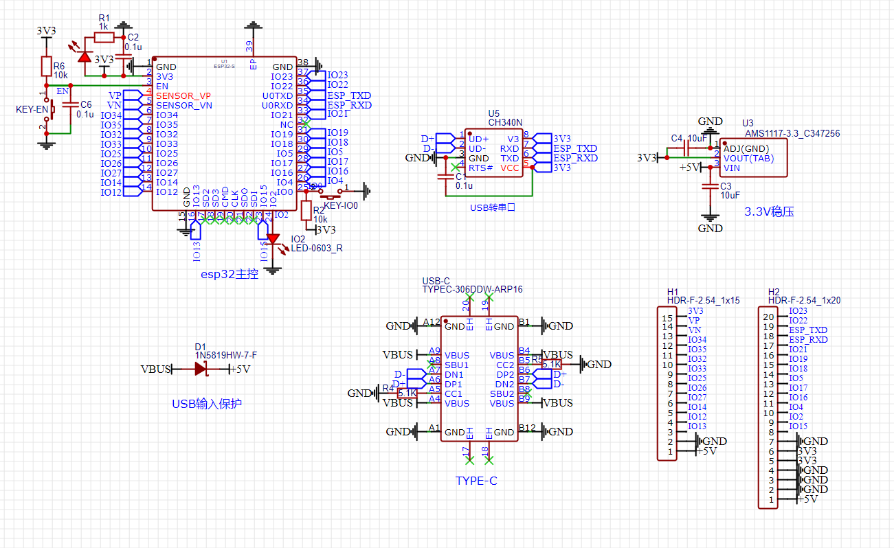
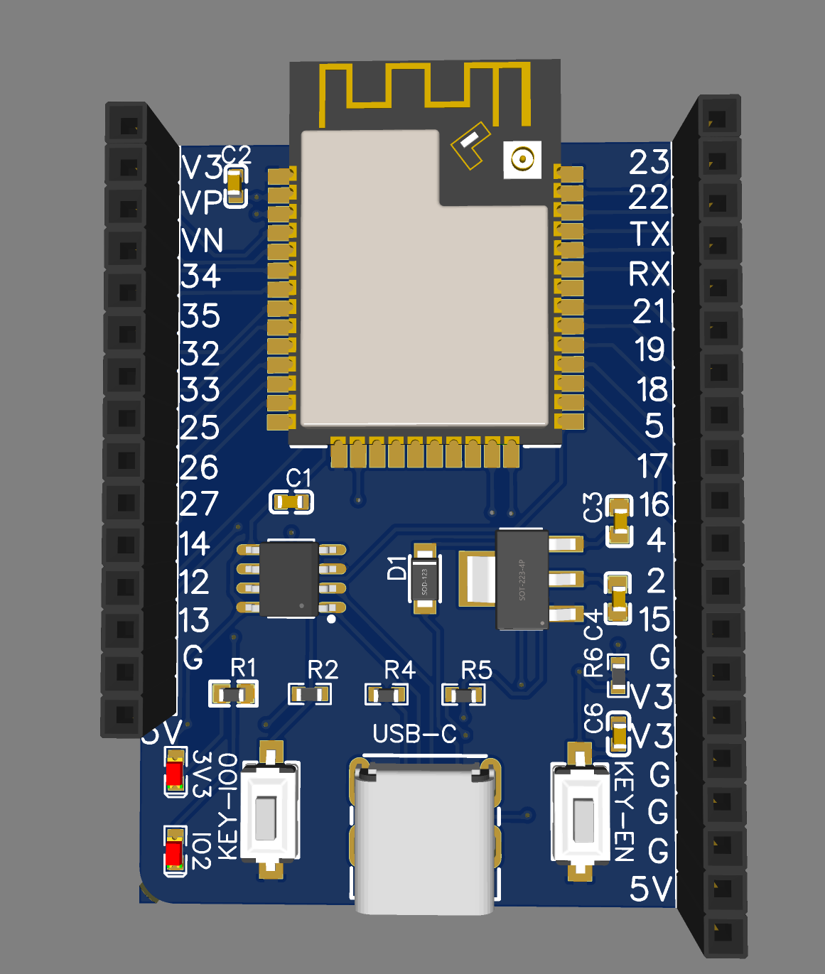
改进版原理图 对于常见的esp32开发板我做出了一些修改:
针脚改为向上的母座,减少很多接线的麻烦
usb转串口改为更便宜的ch340等(由于不想要自动下载电路使用的ch340n)
使用直插type-c母座方便焊接
原理图
PCB-3D
这个设计还有一点就是模块化了esp32模组外围电路,包含了启动配置电路等,便于将来直接在其他工程中调用
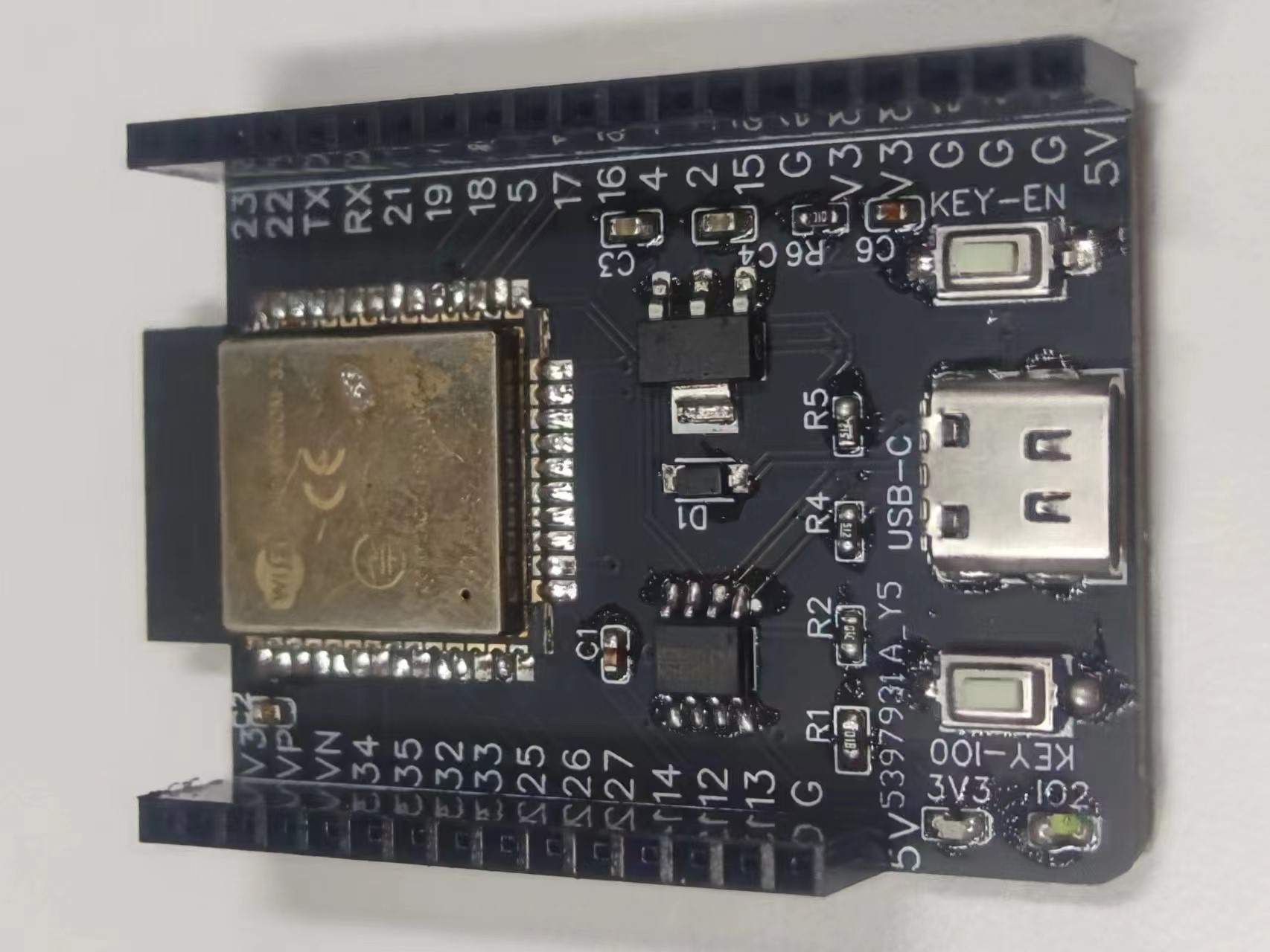
2023.6.29:纪念一下第一个正常使用的esp32开发板焊接完成投入使用之前的每个版本都是自动下载电路出现问题这次直接删掉就成功了
不得不提及一下图片里这个esp32模组的身世,来自于我tb买的esp32开发板,之前一次自制开发板验证过程中准备拆焊买的这个开发板的模组,但是放在焊台上开350度之后就忘记了,二十分钟之后抢救下来发现还能用hhh然后继续用来测试直到现在焊接到了这个新的开发板上
可能遇到的错误 烧录报错 MD5 of file does not match data in flash
MD5 of file does not match data in flash
安装esptool.py:python -m pip install esptool
运行python -m esptool --port COM5 write_flash_status --non-volatile 0 //COM5替换成ESP32连接端口
出现以下输出即表示成功
1 2 3 4 5 6 7 8 9 10 11 12 13 esptool.py v2.4.0 Connecting........_ Detecting chip type... ESP8266 Chip is ESP8266EX Features: WiFi MAC: b4:e6:2d:68:3b:96 Uploading stub... Running stub... Stub running... Initial flash status: 0x0200 Setting flash status: 0x0000 After flash status: 0x0000 Hard resetting via RTS pin...
注意事项:这个命令在进入烧录模式的时候才可以使用,在linux和mac下,一定要使用sudo
参考资料 https://randomnerdtutorials.com/esp32-pinout-reference-gpios/ https://deepbluembedded.com/esp32-pwm-tutorial-examples-analogwrite-arduino/ https://www.jianshu.com/p/6fb40b3d0c6d https://lingshunlab.com/ https://blog.csdn.net/qq_41868901/article/details/104690524 https://blog.csdn.net/supermodule/article/details/129313032 https://blog.csdn.net/weixin_42880082/article/details/121055405 https://blog.csdn.net/weixin_42880082/article/details/120766154 https://blog.csdn.net/qq_41650023/article/details/124674493 https://triority.cc/2023/xbox-python/ https://www.cnblogs.com/greyelectron/articles/16327709.html https://blog.csdn.net/qq_41868901/article/details/106203642 https://blog.csdn.net/qq_27114397/category_7917392.html https://blog.csdn.net/weixin_43353164/article/details/105060630 https://www.yiboard.com/thread-1344-1-1.html https://blog.csdn.net/qq_62361151/article/details/130102202 https://zhuanlan.zhihu.com/p/145369083 https://blog.csdn.net/z755924843/article/details/82704020 https://blog.csdn.net/xq151750111/article/details/115142727 https://blog.csdn.net/Naisu_kun/article/details/86004049 https://lastminuteengineers.com/handling-esp32-gpio-interrupts-tutorial/
